Having NIS-Elements installed and all hardware accessories set up within the  Devices > Device Manager
  window, you can start capturing images. Let's begin with the simplest case.
Turn the connected camera and other devices ON and start NIS-Elements.
Select a suitable hardware configuration on startup.
Make sure the Compact tab is selected with the
 Acquisition
  panel displayed on the right.
Select a lightpath which includes a camera (1).
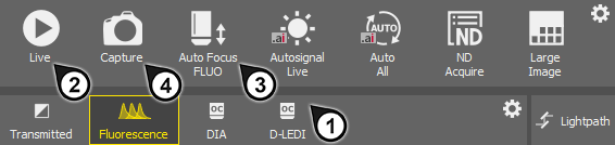
Figure 222.
Display the camera image by the
 Live tool (2).
Adjust Exposure on the camera pad to get a nice image of the scene.
Focus on the scene by the
 Auto Focus tool (3).
Capture the image by the
Capture tool (4).A new image is opened automatically and named “Captured ...”.

Figure 223. Light path tool bar for a configuration with two different cameras
Buttons for switching between lightpaths available for the current hardware configuration are displayed below the tool bar of the Acquisition panel. An icon is displayed on each button to indicate the type of lightpath:
 Brightfield
 Bright-field microscopy acquisition.
Transmitted Transmitted light microscopy acquisition.
 , DIA, EPI
 General acquisition based on optical configurations. Different optical configurations can be created within such a lightpath.
 Fluorescence
 Multichannel acquisition based on “experiment settings”. With this concept, the user specifies a set of fluorescence dyes to be used within an experiment. The program calculates the hardware settings automatically.
See Multi-channel image acquisition via experiment settings.
 , DIA, EPI
 General observation lightpath. Different optical configurations can be created within such a lightpath.
 Lightpath
 Click this button to open the Lightpath Scheme  panel which visualizes the current lightpath and may indicate possible errors in the setup.
In case there are some lightpaths you will not use, you can hide them from the tool bar. Click  Configure... or using the
  RMB anywhere in the tool bar and select to open the User Visible Buttons window.
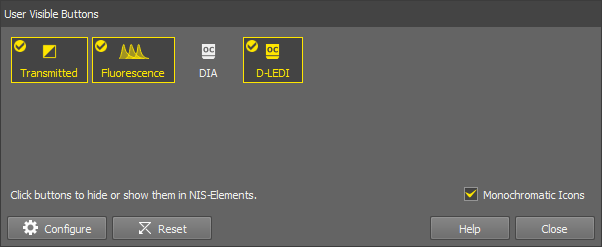
Figure 224.
(De)select any lightpaths you do not want to display. The ones with the tick icon will be displayed in the tool bar.
Optionally change the icon color (color or monochromatic icons).
If you are a user with the privilege Modify devices and light paths, you can even hide some light paths entirely. To do this, use the
Configure button in the same dialog window to open the Button Order and Visibility System Defaults window.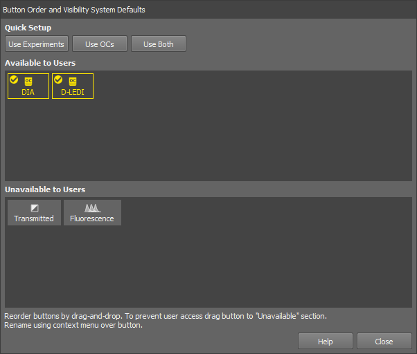
Figure 225.
Drag the buttons to the bottom area to hide them to the users. Change the order of the available buttons by moving the buttons in the Available to Users area. Quick single-click button setups are available in the Quick Setup section in the top of the window. Rename the button in the context menu over the button.
Click to confirm the selection.
Select a lightpath button with the icon . A tool bar with optical configurations appears below the lightpath buttons. The usage of optical configurations (OCs) within the Acquisition panel is the same as in the previous versions of the software where optical configurations were global. The difference is that only OCs created within the currently selected lightpath are displayed here and in the main tool bar of NIS-Elements. Other optical configurations are available only after switching the lightpath.
Note
To change the described default behavior, click RMB in the OC tool bar and select Show OCs from all Lightpaths. Moreover, particular OCs can be hidden from the tool bar by the Select Visible Configurations command from the same context menu.
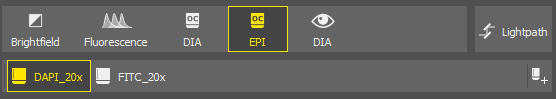
Figure 226.
 Add
Add Click this button to call the Calibration > New Optical Configuration  command.
Select the Fluorescence lightpath to display the Experiment panel. Here you can define different presets for multi-channel acquisition.
Let's suppose you are creating a simple experiment consisting of channels DAPI, FITC, TRITC.
Select a lightpath
Make sure the
Fluorescence light path is selected in the Acquisition panel.Add a new experiment preset
Click on the
 Add button in the Experiment panel.
Specify channels

Figure 227. Experiment wizard.
Type “DAPI” in the first search field, select the actual dye you will be using and confirm it by Enter. Another search field appears. Add the FITC and TRITC dyes as well. Optionally, select the Use Brightfield Channel box to capture the brightfield channel too.
Confirm the experiment settings
Click to close the window. The newly created experiment will be activated and a button for each channel will appear below the selection box.
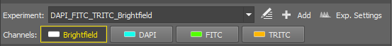
Figure 228. Experiment panel
Single Channels and All Channels options are present by default.
All Channels - automatically calculates the possible dyes for acquisition based on the experiment excitation wavelength and filter settings. All channels are acquired during the capture.
Single Channels - all possible dyes are calculated, however just the single (selected) channel is acquired during the capture.
Adjust light power and exposure for each channel
Below the
Experiment panel, the experiment pad (Experiment pad) appears instead of the usual camera pad. It consists of a simple control panel for each channel where illumination power and exposure time can be adjusted. Only one channel can be active at a time.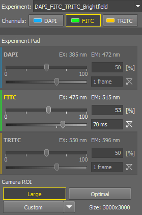
Figure 229. Experiment Pad
You can:
Run the live image by the
Live tool.Activate the split view by the
 Split Components tool in the image tool bar.
Switch between the channels within the experiment pad and adjust the exposure and illumination power so that the live image is as you need. If you need to make any changes in the preset, use the
Exp. Settings button, to edit it. See Adjusting and managing experiments.Use the
Capture tool to capture a single multi-channel image.
The Experiment pad is different for different microscopes. For Nikon Ji, it looks as follows:
See Microscopes.
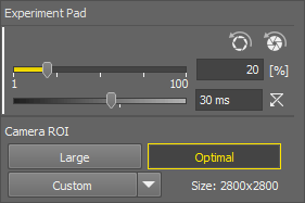
Figure 230. Experiment pad
The first slider sets the exposure of the connected camera. Move the slider or enter a specific value into the edit box.
The second slider sets the illumination power of the connected illumination device.  resets the illumination power value to default.
 Apply Opened Aperture Brightfield Service Settings ,
  Apply Closed Aperture Brightfield Service Settings
 Preset values of exposure, light power and condenser selection can be defined for each objective in the Devices > Service Settings  window. This button applies the preset of the current objective. If the experiment settings are different than the service settings, an exclamation mark is shown on the experiment button.
Note
The Show Closed Aperture button for 4x objective on ACQ pad option must be selected in the Devices > Service Settings window to display the latter button.
Camera ROI
The system offers the users three pre-defined ROIs and a custom one. All of the ROIs are available only if they are different from each other.
ROI set to the size of the full sensor.
Defines the ROI size (Define ROI...), specifies which buttons are shown on the pad (ROI Buttons), changes the custom ROI size and saves (Save ROI...) or loads saved ROIs (Load ROI...).
The experiment is characterized solely by dyes, and the system automatically identifies the appropriate light path configuration for each dye. The light path settings can be adjusted manually by opening the  Edit window:
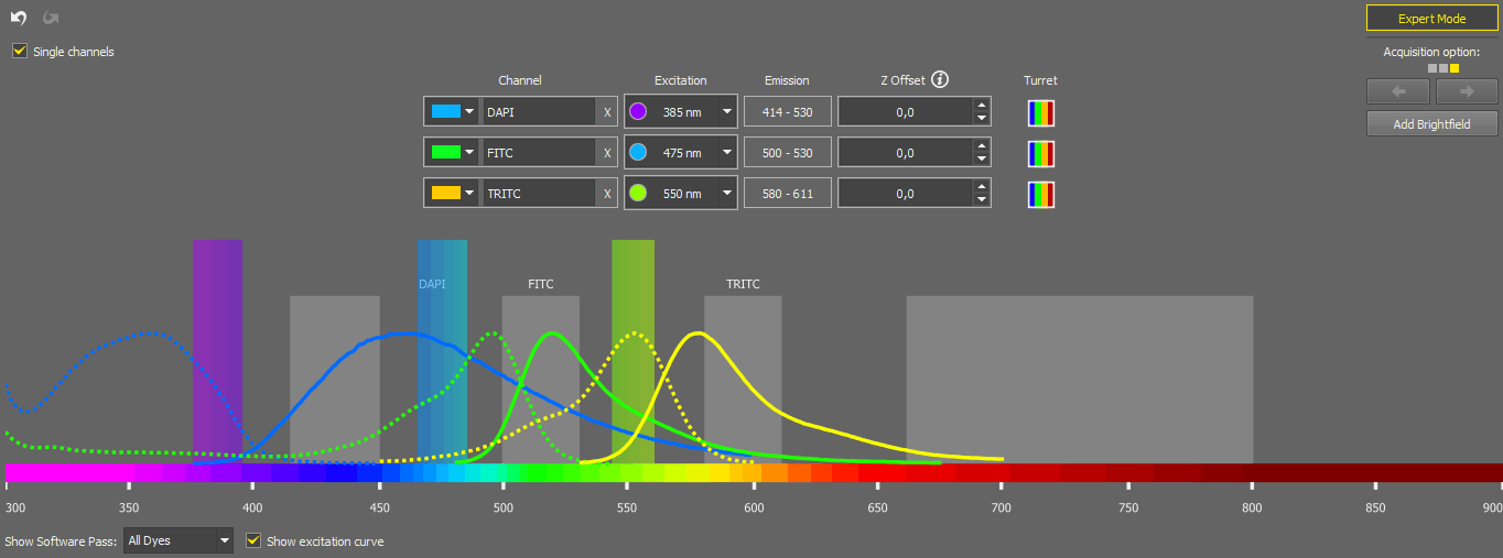
Figure 231.
Here you can change the color of a channel, rename it, delete it (), change its excitation wavelength (when switched to ), change the Z offset, or add a Brightfield channel ().
The Single Channels experiment is created to efficiently examine an unknown sample by enabling the selection of any light source wavelength and viewing the results in a live window with a single channel. While the setup is similar to the corresponding channel in the "All Channels" experiment, operating it is simpler due to having a LUTs graph and a single channel tab in the live window. Checking the Single channels option means that even in a multi-channel experiment, only one channel is captured at a time. When you create a new setup (in the Device Manager) for the first time and have already created a reasonable All Channels experiment, the system automatically generates a corresponding Single Channels experiment.
The behavior of the “Single Channels” experiment mirrors that of turning off all channels except the current one in the “All Channels” experiment, which can be done through the context menu over the channel buttons. To disable a channel use the RMB over the channel button and select Off. If you check the option Channel Selection via Left Mouse Button (found in the General tab of the Configure dialog), a simple  LMB can be used to turn the channels on and off.
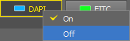
Figure 232.
Tip
From the context menu over each channel, you can disable and hide any undesired channel from the Experiment pad. To re-enable a channel, open the context menu on the channel button and switch it to On.
The Acquisition option on the right means that for a given experiment (given dye) a number of possible configurations (each one shown as a square) have been found and can be used for acquisition. Move between the configurations using the arrows.
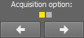
Figure 233.
The spectrum preview below shows the software pass for the channel selected in the drop-down menu. Excitation curve can be shown in the preview by checking Show excitation curve. Once you are done with the adjustments, click to confirm the settings.
The experiments can be managed through Exp. Settings:
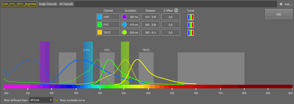
Figure 234.
Here you can check all the channel information for each channel selected in the first drop-down menu. More channels can be added using Add (see Multi-channel image acquisition via experiment settings). By clicking , you are redirected to the editing window described above.
Parfocality ensures seamless transitions between microscope objectives with minimal or no refocusing, allowing for consistent focus adjustments during magnification changes. Experiment parfocality can be set in three different ways:
Automatically - using the context menu command over the image area (Experiment Parfocality Correction > Find Automatically).
Manually - by setting the Z Offset values in the
Edit window.For experiments excluding brightfield - using the context menu command over the image area (Experiment Parfocality Correction > Save Channel Parfocality Offsets).
Sample navigation is integrated into the Compact layout to control mainly the Ji and Ti2 microscope systems. Relying on the geometry of the known Ji/Ti2 microscope holders, this improves the identification of sample location, with added functionality for automatically scanning of slides, wellplates, and dishes. The pad can be undocked (opened as a separate window) using the  button.
Sample navigation is also integrated into JOBs as tasks used for defining labels, dosing, and well selection:
 Use Well Selection from Sample Navigation
 Create Well Selection from Point Set
 Export Well Labeling to Sample Navigation
 Export Well Selection to Sample Navigation
 Import Area From Sample Navigation
Note
To use the Sample Navigation panel with the Nikon Ti2 microscope, Z focus has to be calibrated first (see Service settings ).
Note
Features vary among different software packages and used hardware.
Please refer to Feature dependency on hardware and packages for a detailed comparison of the available functions for each software package and hardware combination.
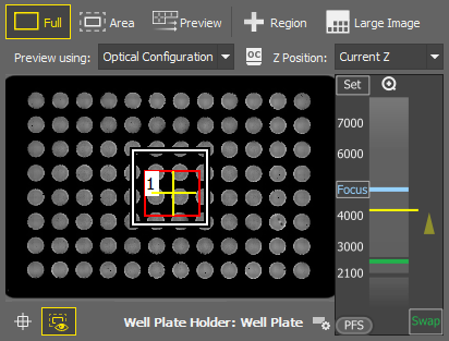
Figure 235. Stage tab
 Area
Area Displays the preview of the scanned area of interest (typically a slide or a coverslip area usable for imaging). To edit the AOI, select the  Full mode and click on the AOI edge. Confirm the AOI by RMB.
Both the Full and the Area areas can be scanned separately, typically the Full area is scanned just once and the Area area is scanned multiple times (per each sample).
 Preview
 Scans the Full/Area sample preview based on the selection made in the Preview using drop-down menu.
The capture depends on the selected holder and uses the bright field settings set in the Service Settings window ( Devices > Service Settings ).
Region This tool is used to draw one or more regions in the preview area which are then scanned using the  button. Description of the specific tools can be found here: Drawing tools. If no region is defined, it is possible to scan just the Area. The newly improved Focus Surface generator is integrated into the built-in job used for the scanning.
Large Image Scans a large image over the drawn region(s).
Scanning # ROI(s) - shows the number of ROIs to be scanned.
Built-in Job scans the large image using the built-in method whereas Custom Job enables the user to scan the large image using the selected custom JOB.
See JOBS and HCA.
Generate Focus Surface finds the optimal focus surface and performs the large image scan on this surface whereas Current Z-Level scans the large image on the current Z position.
Create Large Image stitches the large image together creating one large image file, whereas Store Single Images does not stitch together, instead a multi-point file is created.
Specifies the settings for the Preview scan.
Current settings perform the scan with the current light path and experiment settings, Optical Configuration scans using the selected optical configuration (click Select optical configuration... to select it) and Service Settings scans a bright field image based on the parameters set in Service Settings (Service settings ).
This selection further specifies the Z position used for the Preview scan.
Choose Sample Swap (sample swap position defined during the Z calibration) or Current (current Z position).
 Show FOV
 Shows/hides the camera field of view in the preview area.
 Show Area
 Shows/hides the area of interest (e.g. a coverslip) in the preview area.
 Select Holder
 Option to choose the relevant holder from the database.
The holders on the Ji system are calibrated via the Ji Tools utility, while the calibration of the holders on the Ti2 system is done through the Service Settings (Service settings ) dialog in NIS-Elements. The Z coordinates used in automatic functions (Detection, Scanning, etc.) for the selected holder are saved in the Service Settings (Service settings ).
Context menu over the Preview (similar for all sample holders)
Starts scanning the area of interest (white rectangle).
Starts scanning the large image.
Opens the Auto Scale Settings window where the Low and High fields determine how many of all pixels of the picture are left outside the LUTs sliders when Auto LUTs is applied (0-10%). See also Auto Scale Settings.
Context menu over a Region
Starts scanning the large image inside the selected ROI(s).
Renames/selects/deletes the ROI.
Selects/deselects/deletes all ROIs at once.
Starts scanning the area of interest (white rectangle).
Starts scanning the large image.
Opens the Auto Scale Settings window where the Low and High fields determine how many of all pixels of the picture are left outside the LUTs sliders when Auto LUTs is applied (0-10%). See also Auto Scale Settings.
Z Navigation
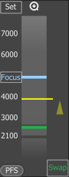
Figure 236. Z Navigation
The vertical column represents the entire Z dimension, with the yellow horizontal line representing the current position, the blue line indicating the Focus position, and the green line denoting the swap position. Place your mouse cursor over the vertical column, then scroll the mouse wheel to adjust the current (yellow) position or double-click a position to move to it.
Sets the current Z position as the “Focus” position. A tool tip over the button shows its Z value.

 Zoom in/out
This button appears only when working with slide samples and resets the focus value to default.
Moves the Z stage to the predefined focus position. A tool tip over the button shows its Z value.
(requires: Local Option)
Turns the perfect focus system (PFS) on and applies the current PFS offset.
Moves the stage to the swap position - a safe position for changing the samples. A tool tip over the button shows its Z value. This value is calculated automatically during the holder calibration and cannot be changed.
There are various combinations of hardware, microscopes, and NIS-Elements packages activating some Sample Navigation features. The following table outlines the different options. Each option is closely described below the table.
Table 4.
| Hardware | Ar package + 6D module + JOBs module | Ar package | Br package | D package |
|---|---|---|---|---|
| Ji/Ti2 microscope, Mono camera supporting fast scan | Option 1 | Option 2 | Option 2 | Option 5 |
| Ji/Ti2 microscope, RGB camera supporting fast scan | Option 3 | Option 5 | Option 5 | Option 5 |
| Ji/Ti2 microscope, Mono/RGB camera not supporting fast scan | Option 4 | Option 6 | Option 6 | Option 6 |
| Ni-E/other microscope + MZH+Aux, Mono/RGB camera supporting fast scan | Option 3 | Option 5 | Option 5 | Option 5 |
| Ni-E/other microscope + MZH+Aux, Mono/RGB camera not supporting fast scan | Option 4 | Option 6 | Option 6 | Option 6 |
| Ni-E/other microscope, Mono/RGB camera | Option 4 | Option 6 | Option 6 | Option 6 |
See Cameras supported for continuous movement.
Important
Service Settings dialog is available only:
in Ar and Br packages.
for Ji and Ti2 microscopes.
for Mono cameras from the fast scanning supported list (see Cameras supported for continuous movement).
Fast scanning is supported:
on selected cameras (Mono or RGB) only (see Cameras supported for continuous movement).
on selected XY Stages (Ji, Ti2, MZH+Aux).
Using the Custom job is available only for license containing Ar + 6D + JOBs.
Fast scan can always switch to the step-by-step mode if the application determines that it will be faster.
List of Options:
Built-in Job
Custom Job
Generate Focus Surface
Current Z-Level
Create Large Image
Store Single Images
Current Settings
Optical Configuration
Service Settings
Sample swap
Current Z
Current Settings
Optical Configuration
Service Settings
Generate Focus Surface
Current Z-Level
Create Large Image
Store Single Images
Current Settings
Optical Configuration
Service Settings
Sample swap
Current Z
Current Settings
Optical Configuration
Service Settings
Built-in Job
Custom Job
Generate Focus Surface
Current Z-Level
Create Large Image
Store Single Images
Current Settings
Optical Configuration
Sample swap
Current Z
Current Settings
Optical Configuration
Built-in Job
Custom Job
Generate Focus Surface
Current Z-Level
Create Large Image
Store Single Images
Current Settings
Optical Configuration
Current Z
Current Settings
Optical Configuration
Generate Focus Surface
Current Z-Level
Create Large Image
Store Single Images
Current Settings
Optical Configuration
Current Z
Current Settings
Optical Configuration
Generate Focus Surface
Current Z-Level
Create Large Image
Store Single Images
Current Settings
Optical Configuration
Current Z
Current Settings
Optical Configuration
Scanning is performed by the continuous movement (fast). “Large Image” can be scanned by a custom or a built-in job (scanning routine).
Available features for option1 :
Full mode) Full mode) Area mode) Scanning is performed by the continuous movement (fast). “Large Image” can be scanned by the built-in job (scanning routine) only.
Available features for option 2:
Full mode) Full mode) Area mode) Scanning is performed by the continuous movement (fast). “Large Image” can be scanned by custom or build-in job (scanning routine). Service settings are not available for this configuration.
Available features for option 3:
Full mode) Full mode) Area mode) Scanning is performed by the step-by-step movement (slower). “Large Image” can be scanned by the custom or built-in job (scanning routine). Service settings are not available for this configuration.
Available features for option 4:
Full mode) Full mode) Area mode) Scanning is performed by the continuous movement (fast). “Large Image” can be scanned by the built-in job (scanning routine) only. Service settings are not available for this configuration.
Available features for option 5:
Full mode) Full mode) Area mode) Scanning is performed by the step-by-step movement (slower). “Large Image” can be scanned by the built-in job (scanning routine) only. Service settings are not available for this configuration.
Available features for option 6:
Full mode) Full mode) Area mode) Accessibility of the some function depends on the automatic scanning settings (Overview and Plate scanning in Sample Navigation) made in the Service settings window.
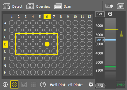
Figure 237. Well Plate tab
Click
 in the Compound area to define a compound - name it and hit Enter.
Note
Negative and Positive Control labels are already defined.
Optionally create a compound group by clicking
in the Group area. Name the group and hit Enter. All the defined compounds are added to the group.Set the compound units in the Units drop-down menu.
Select a group of wells in the well plate preview and click on a label. Repeat this for all defined labels.
Fill in the concentration in each labeled well. Values can be entered manually, copied from other wells or well series or filled by expanding the yellow selection.
Confirm the Labeling and Dosing by clicking .
Note
To save the label/dosing definition into the database, click
 in the top right corner and use the saving manager.
Click on the
icon to define a new custom label - name it and hit Enter.Change its color by clicking on the color rectangle.
Select a label so that it is highlighted by a yellow rectangle.
Click or click and drag in the well plate preview to mark the wells with the selected label. Click on the labeled well again to remove the label.
Tip
While holding down Ctrl you click and drag in the preview to remove the labels.
Click to confirm the labeling.
 Detect
 Automatically detects the well plate geometry using AI (artificial intelligence).
 Overview
 Scans the overview of all wells with the bright field settings set in the Service settings window. Image of the well center is displayed in the preview for each well.
 Scan
Scan Captures high-resolution images of those wells selected via the  Select Wells tool. Once clicked, a form appears where you should select acquisition options. Options available for the current configuration selected in the Acquisition panel are available.
Built-in Job
Enter a unique ID of the well plate to be scanned.
Select the size of the large image (MxM tiles) to be scanned in the center of each well.
Select the method used for focusing.
Custom Job
Select a job from the database used for the scanning and click .
 Label Wells
 Opens the Labeling and Dosing window.
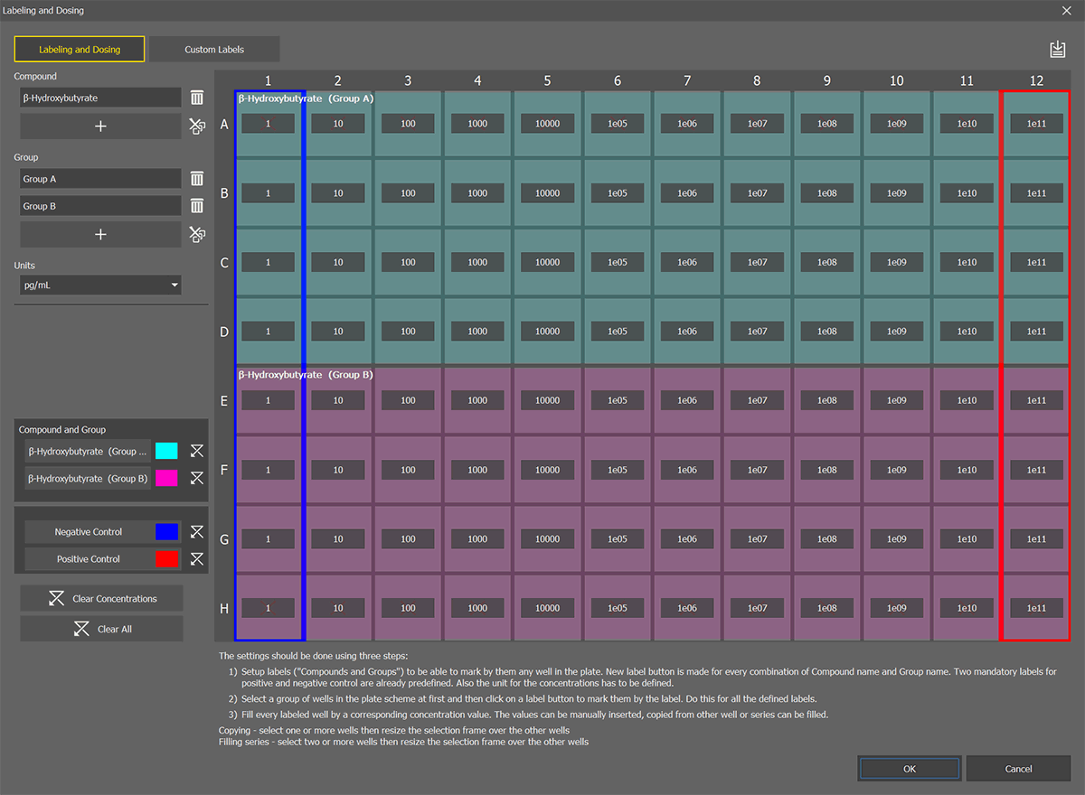
Figure 238. Labeling and Dosing window.
Labeling and Dosing (data used for analysis)
Custom Labels (not used for analysis)
Select Wells Opens the Acquisition Selection window where you can select wells for acquisition. Hold Shift to add the clicked wells to the selection. Hold Ctrl to remove the clicked wells from the selection.

Displays the summary labeling and selection information.
 Scheme
 Displays a well plate scheme.
 Images
 Displays captured images as the wells.
 Overlay
 Displays the labeling, dosing and well selection layers over the preview image.
 Move to Exact Position
 Moves the stage to the exact position clicked in the preview area.
Select Holder Option to choose the relevant holder from the database.
This tab supports navigating in the ND2 documents having well plate metadata created in the Smart Experiment application.
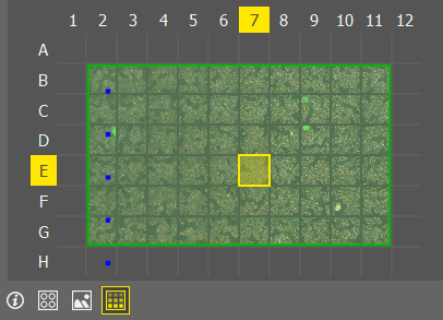
Figure 239. Document tab
Displays the summary labeling and selection information.
Scheme Displays a well plate scheme.
Images Displays captured images as the wells.
Overlay Displays the images together with defined labels and selection.
The Devices > Service Settings window allows adjustments to the microscope and camera settings which are applied to the well plate overview scanning. Settings adjusted here also influence the acquisition controls in the Acquisition panel.
Well plate overview scanning is used by the Smart Experiment module and by the View > Acquisition Controls > Sample Navigation  panel.
Note
Sufficient user rights are required for this function to be accessible.
Depending on the microscope model, some of the options could not be available.
Overview and Plate scanning in Sample Navigation (Nikon Ti2)
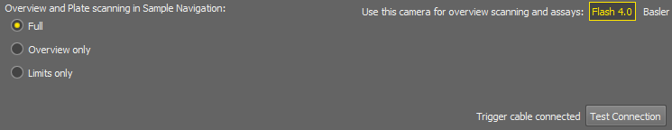
Figure 240. Overview and Plate scanning limits.
 How to setup Ti2
 Opens the GITHUB DOCUMENT describing how to set up the Nikon Ti2 microscope with software applications utilizing well plates, such as cell detection Ai tools, sample navigation, and custom jobs.
Sets the limits to the user controlling the Sample navigation panel.
All functions of the panel are available.
Limits the control to a basic overview and Overview or ROI scanning and re-scanning. Z-Reference Only
Leaves the user with just a simple stage observation and possibility to change the sample holder.
Select a camera used for scanning the overview in the Sample Navigation and Assay.
Click this button(s) to test the triggering cable connection(s).
Camera
Specifies the scanning settings for the particular camera.
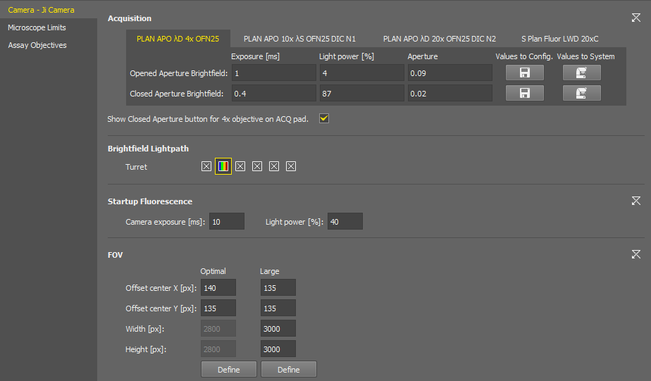
Figure 241. Service Settings for the Nikon Ji.
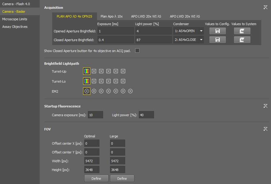
Figure 242. Service Settings for the Nikon Ti2.
Note
Exposure time for the 4x objective and the Closed Aperture exceeding 800 µs may result in blurred images in the well plate overview.
It may also cause some functions, such as the NIS.ai > Preprocessing > Cells Presence.ai GA3 node, to not work properly.
You can set the exposure time, light power, and select a condenser or aperture individually for each objective of the current nosepiece configuration. Switch the tabs with the objective names to move between the objective settings.
The button activates the edit mode, allowing the user to save the complete camera settings in the same manner as they are stored in Optical Configurations. When the edit mode is enabled, two additional buttons become available:
 Values to Config.
 Loads the current brightfield acquisition settings from the system to the configuration window.
 Values to System
 Sets the brightfield acquisition settings defined in the configuration window to the system.
Shortcut buttons for applying the opened and closed aperture values ( ) are available in the Experiment pad for brightfield experiments.
Brightfield settings are also used in JOBs.
Select the filter changer positions to be used in the experiment.
Camera exposure and light power values used for the start of the AutoSignal.ai algorithm.
These ROIs are integrated into the Experiment pad. Both ROIs can be adjusted here using .
Size of this FOV (camera ROI) is calculated automatically for each hardware configuration to prevent shading on image borders. When turned on in the camera pad, it is placed in the center by default. Here you can shift it by defining the offset.
A user-adjustable FOV (camera ROI) which is used with the continuous scanning procedure (e.g. well plate overiew).
Microscope Limits (Nikon Ji)
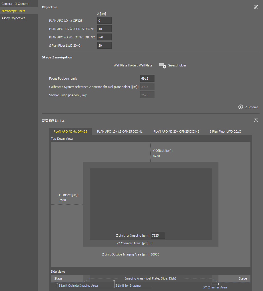
Figure 243. Microscope Limits Service Settings of the Nikon Ji.
Sets Z-position offsets between the objectives.
Specifies the sample holder ( Select Holder) and can be used to adjust the focusing position for the Sample navigation. The Z Scheme explains the focus position.
A drawing of the currently selected sample holder containing its dimensions and movement limits set within the software is shown in this section. Z imaging limit can be set in the middle edit box for each objective (switch the tabs to move between the objectives). Side view of the imaging area is depicted in the bottom.
Microscope Limits (Nikon Ti2)
If the system is not calibrated yet, click .
Select a slide holder for calibration and click .
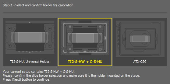
Figure 244.
Even if you plan to use a well plate, the proper Z calibration needs to be done on a slide.
Run
Live and focus on the slide sample either manually or using the Auto Focus. The Z Scheme explains the focus position.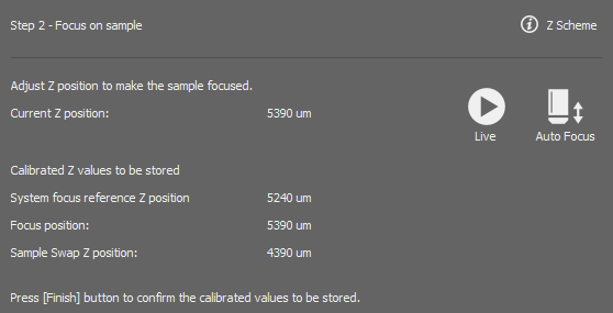
Figure 245.
Once in focus, click .
Sets the Z positions offsets between the current objectives.
Calibrates the Ti2 Z drive so that it can be used in the Sample navigation.
You can repeat the calibration by clicking or adjust the Focus Position in the edit box. The  button sets the value back to default.
Sets the global top limit position for the 4x objective.
Assay Objectives
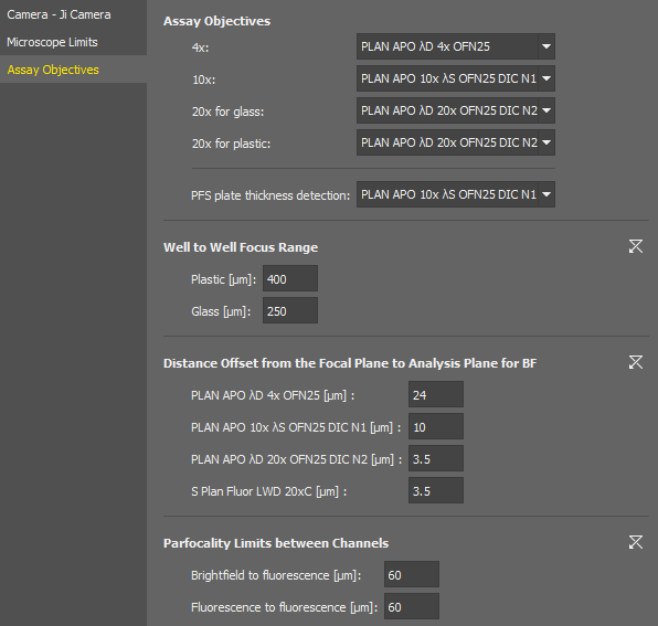
Figure 246. Assay Objectives Service Settings of the Nikon Ji.
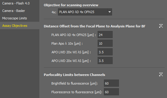
Figure 247. Assay Objectives Service Settings of the Nikon Ti2.
Assays of the Smart Experiment module expect certain objective magnifications for certain tasks.
Here you shall assign actual objective models to be used with the assays.
(Nikon Ji)
The focus range used after moving to an adjacent well. It should be calculated as:
Maximum possible difference between well plate bottoms of adjacent wells caused by inaccuracies in the manufacturing process.
An extension of the range which ensures the auto focus would work even if iw = iwmax.
The distance to be moved after automatic focusing to see the specimen. This value is set for each objective in the nosepiece.
Specifies the maximum allowed difference of focus when switching between different channels within one experiment.