
Note
All non-Nikon stages require the Stage module. The complete list of cameras and devices supported by NIS-Elements is available in a separate document.
FRAPPA (Fluorescence Recovery After Photobleaching and Photoactivation) is a galvo scanning instrument controlled by the Andor FRAPPA dialog window.
This combo box is used to select a stimulation group. Each stimulation group can contain many stimulation ROIs.
Specifies the time for illuminating one pixel of the Stimulation Group.
Opens the FRAPPA Configuration dialog window.
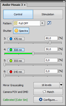
Figure 115.
Andor Mosaic 3 pad controls the Andor Mosaic 3 module which enables multi-point photostimulation simultaneously in arbitrary areas and points of the sample. It consists of two logical sections - Control and Stimulation.
Control Section
Selects one of the predefined patterns and user ROI/DMD patterns. Full ON / Full OFF turns the whole DMD area on/off. Grid displays a calibration grating - also used during calibration.
 Pattern Manager is used for loading patterns from an image file (.bmp, .tiff, .tif, .stk, .lim, .png), organizing patterns, pattern mapping and metadata viewing.
To assign ROI(s) to a stimulation group (S1-S3), right-click over the ROI(s) in your image and select Use as Stimulation ROI: S1-3.
To save a pattern created on the current image with a calibrated DMD, right-click over your ROI(s) and select Export as DMD pattern.... Name your pattern file and specify where to save it. Once you click it is automatically added to the Pattern Manager and Pattern drop-down menu.
If the stimulation device is set as active ( Applications > 6D > Device for Stimulation: [Device Name]), ROIs with gray levels can be used. Specify the number of levels (see Mirror Grayscaling below) and define the gradient in the Intensity ROI Properties window evoked by right-clicking over the stimulation ROI(s).
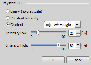
Figure 116. Intensity ROI Properties dialog window
Use Constant Intensity to fill the whole ROI with a defined grayscale intensity level or switch to Gradient and choose its direction and extreme values. Once confirmed, information about the selected values is shown in the caption of the stimulation ROI.
Warning
Andor Mosaic 3 requires 50 ms to display the 256 level (8-bit) grayscale pattern. Set your camera exposure time to a multiple of 50 ms to see the pattern correctly. If you do not synchronize your camera exposure time you will see pattern flickering.
 Shutter
 This button behaves like a shutter. If it is turned on, the physical device turns the DMDs into position defined by the selected stimulation pattern.
Click on the arrow of the button and select the mirror grayscaling level suitable for your grayscale pattern. Then click on the button to activate the chosen grayscaling.
Note
Illumination sequence supports only the 1-bit level grayscaling mode (mirror grayscaling button needs to be unselected).
 Match button matches the field of view of the camera with the DMD extent creating the largest camera ROI fully covered by the DMDs. All digital micro mirrors lying outside the camera FOV are turned off. If the camera FOV is larger than the DMD area and the camera chip is completely covered by the DMDs, the FOV is cropped to the largest horizontal rectangle covered by the DMDs. To maximize the stimulation area make the camera FOV parallel to the DMD area by manually rotating the mounted camera and clicking this button.
 Configure
 Opens the DMD Configuration dialog window used for selecting the HW Interface, associated devices, laser lines, switcher, shutters and for calibrating the DMD device. Calibration configurations highlight (red text) the microscope settings not matching the calibration.
If the device is not calibrated (red notification is displayed), start by clicking  Configure... and choose one of the calibration methods. Auto Calibration is recommended - just follow the instructions in the Autocalibration dialog. Manual Calibration is suggested for advanced users. Calibrations can be deleted any time by clicking
  .
.
Inside the DMD Configuration window, select your HW Interface, Illumination device in the Light combo box, choose your laser lines, switcher, shutters and then click .
Stimulation Section
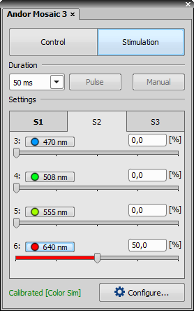
Figure 117.
Specifies the time duration during which the stimulation pattern is on.
This button activates sample stimulation using the selected stimulation group for the time period specified in the duration combo box. When the stimulation time runs out, the pattern is automatically turned off. If Toggle is selected in the duration combo box, this button works as a two position switch (on/off).
Turns on stimulation only when this button is pressed.
These tabs represent stimulation groups. Each stimulation group can contain many stimulation ROIs. Information about selected illumination lines and their illumination power is stored.
Illumination Sequence Interconnection
To be able to control Andor Mosaic 3 through Illumination Sequence (Illumination Sequence), you have to switch the HW Interface to USB/PCIe + Ext Trig in the DMD Configuration dialog inside the Device Manager ( Devices > Device Manager  ).
).
Andor Mosaic 3 with other stimulation devices
Only one of scanning type stimulation device (including Confocal Galvano Scanner, MiniScanner and FRAPPA) and DMD device can be configured. Stimulation by scanning type stimulation device cannot be used when you add a DMD device (Nikon DMD, Andor Mosaic and Mightex Polygon 400) to the system. Please change the system configuration by removing the DMD device using Manage devices when scanning type stimulation device is required.
(requires: Local Option)
The X-Light Pad dialog window is used to control the CrEST X-Light spinning disk.
Turn the motor of the spinning disk on/off.
Choose one of the three filter wheel positions.
Manage your filters by clicking this icon.
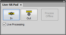
Figure 118.
The Live-SR Pad controls the Live Super Resolution Module by Gataca Systems. This device is used with a spinning disc (Yokogawa CSU-W1 or Yokogawa CSU-X1). To obtain a super resolution image, a hardware approach and software processing is combined. The device is connected through NIDAQ and its TTL line has to be named correctly in order to control the device via the Live-SR Pad. Make sure the registry key TTLName is set to LiveSRTTL found in:
\HKEY_LOCAL_MACHINE\SOFTWARE\Laboratory Imaging\Misc\Gataca LiveSR
Turns on/off the hardware device.
If the data were acquired with the hardware on and processing off, these data can be later processed using this button.
This check box turns on the software processing. It is enabled only when the device is turned on.
(requires: Incubator NIS Special No.8)
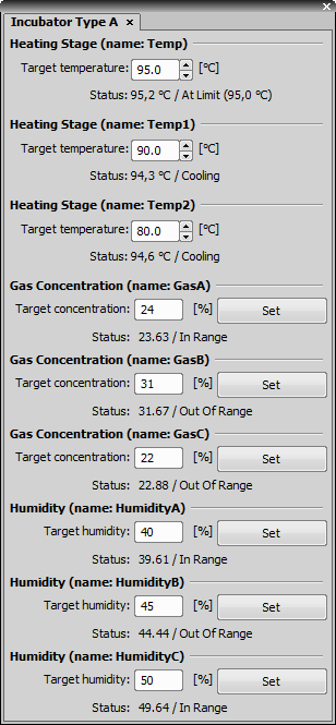
Figure 119.
This pad controls the Incubator device.
Control Panel Options
Each edit box enables the user to set the target temperature of the particular heating stage.
Enables the user to set the target gas concentration.
Enables the user to set the target humidity value.
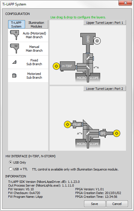
Figure 120. Ti-LAPP System
Ti-LAPP system presents the functions of EPI-Fluorescence, TIRF and Photostimulation as individual modules, which can be combined to suit various observation requirements. Ti-LAPP System dialog window is used to configure the complete Ti-LAPP layout using virtual LAPP and Illumination modules.
Supported LAPP System Modules
Supported Illumination Modules
H-TIRF (see: How to use LAPP H-TIRF)
H-TIRF Direct XY-F
E-TIRF
TIRF
DMD (see: How to use Nikon DMD)
EPI
FRAP
N-STORM
N-STORM Direct XY-F Zoom
Other
LAPP System Restrictions
Only one DMD module can be used.
Only one H-TIRF module can be used.
Only one N-STORM module can be used.
H-TIRF and N-STORM cannot be used at once.
Only one motorized sub branch can be used.
Motorized sub branch can be connected only to a motorized main branch.
Maximally 5 modules can be used at once.
Physical layout restrictions due to interference of the modules and their operability may occur. Please contact your local Nikon dealer for layout solutions.
Configuration requirements
When using a motorized branch, its controller port has to be assigned in the Ti-LAPP System window.
LAPP/DMD controller guards whether H-TIRF/DMD is connected or not. If these devices are configured in the Ti-LAPP System window and not physically connected, the configuration cannot be saved.
If motorized main branch or motorized sub branch is not connected, configuration using these branches can be forced, however this may not be allowed by the controller.
Laser scanner attachment used for ROI laser stimulation, activation, bleaching, ablation and cutting experiments can be used when having the XY Galvo device license. The attachment should be mounted to the LAPP port. It has two galvano motor mirror scanners to quickly move a laser beam across the center of the FOV. NIS-Elements controls the position of both mirrors through two analog output lines of a NIDAQ board (Device Manager Settings). The laser is switched on/off synchronized with the ROI scanning. For more information about using the XY Galvo device please see the NIS-Elements Galvo Scanner License brochure.
Click Configure in the LAPP Pad
Click
Configure... in the LAPP Pad or select LAPP in the Device Manager and click to open the Ti-LAPP System Configuration dialog window.Click /: / buttons and set connection ports
Specify which port is used for the connection between the upper/lower main branch and the controller.
Drag and Drop the Main Branch
Based on your real LAPP configuration, drag and drop the Main Branch (Auto or Manual) from the LAPP System tab into the right area above the microscope. Suitable locations are highlighted with a dashed silhouette. Main branch can be easily inverted by 180° clicking on this
 icon. Both upper and lower layers can be mounted.
Drag and Drop the Sub Branch
Drag and drop the Sub Branch (Fixed or Automatic) from the LAPP System tab into the right area above the main branch to match your real LAPP configuration.
Set the Main Branch and Motorized Sub Branch mirrors
Click on this
 icon and set up the mirrors of your Main Branches or Automatic Sub Branches. Choose the Mirror Type from the combo box and enter its parameters into the Mirror details edit box (if available). Suggested format is shown below (e.g.: 50/50).
Drag and Drop Illumination modules
Switch to the Illumination Modules tab and drag and drop connected illumination devices close to the desired ports of your main/sub branches. You can rename your illumination modules by right-clicking on them and selecting Rename.
Click on the circle of the illumination device to select its light source
Click on
 to specify the Light Source (light port) and Switcher (if available).
Save your configuration
Once you finish your LAPP configuration which matches your real setup, click to save your configuration.
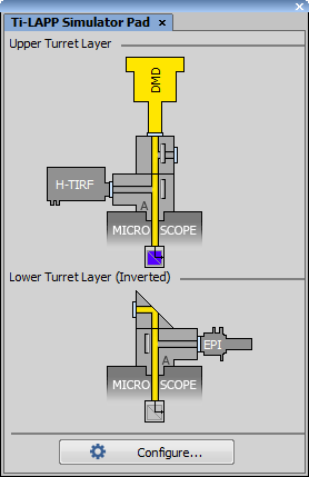
Figure 121.
The yellow light path in the Ti2 LAPP Pad shows the light path from the illumination device to the filter changer. This path can be adjusted by clicking either on the mirror icon or on the illumination module itself.
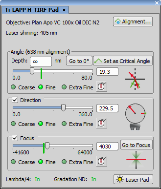
Figure 122. LAPP H-TIRF Control Pad
LAPP H-TIRF Pad controls the H-TIRF module. If “<invalid objective>” is displayed in the TIRF Alignment combo box, make sure your Nikon Ti microscope is connected and is using an objective suitable for H-TIRF (check your Ti Pad).
Supported objectives
Plan Apo λ 100x Oil (MRD01905)
Plan Apo VC 100x Oil DIC N2 (MRD01901)
Apo TIRF 60x Oil DIC N2 (MRD01691)
Apo TIRF 100x Oil DIC N2 (MRD01991)
Automatic Alignment
Click
 Alignment... in the Ti-LAPP H-TIRF Pad. TIRF Alignment dialog window opens.
Click
 Assist Focus in the Focus section. The system automatically finds the best focus.
Click
Start Alignment... in the Critical Angle section. 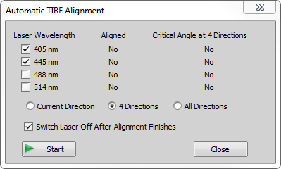
Figure 123. Automatic TIRF Alignment
Select which laser lines you want to align and choose the direction type (4 Directions use 0°, 90°, 180° and 270° whereas All Directions use 72 directions with 5° spacing). Click
Start. The system now finds the zero degree position and critical angle for the chosen directions and laser lines.Confirm the alignment by clicking and the Automatic TIRF Alignment dialog window.
Note
H-TIRF alignment is always associated to a specific objective. To save the current alignment state you can use  Save....
Manual alignment (for advanced users)
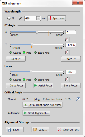
Figure 124. TIRF Alignment
Click
Alignment in the LAPP H-TIRF Pad. TIRF Alignment dialog window opens.In the 0° Angle section move the X and Y sliders to find the zero degree position when the laser beam is projected perpendicular to the ceiling.
Click to save the found value.
In the Focus section move the slider to find the smallest spot size of the beam projected e.g. on the ceiling.
Click to store the found focus.
Assist Focus can also be used to help with finding the focus value which is automatically stored when Assist Focus is finished.Run the
 Live image mode and find your sample using the stage. It is important to precisely focus on the boundary between the slide and the sample in the Z direction. Also the camera settings play a big role when finding the TIRF angle. Low light microscopy principles should be utilized - long exposure, high gain, etc.).
Adjust the Angle slider on the Ti-LAPP H-TIRF Pad for the selected Direction. Try to find the critical angle in a narrow strip where the intensity of the background decreases while the intensity of the slide-sample boundary increases.
Once you find the critical angle, click
 Set and confirm the new critical angle by clicking .
Advanced functions
Switches from aligning All wavelengths to a wavelength-specific alignment. The wavelength can then be selected from the combo box. If you switch to a wavelength that is not currently used for illumination,  Sync Laser can be used to switch the appropriate laser line on.
Sync Laser Turns on only the laser line which corresponds to the laser line selected in the Wavelength combo box.
Advanced Options This button opens the Advanced Options dialog where editing of the Critical Angle and Refractive Index values can be enabled. If checked, edit boxes appear in the Manual row of the Critical Angle section in the TIRF Alignment window. These critical angle values tell the software that the current motor position of the TIRF device corresponds exactly to the new values entered into the edit boxes (degree value with the specified refractive index). TIRF motors are not moved after this angle correction.
Save... saves the current alignment state into the database from which it can be loaded using  Load... or deleted using .
  Clear Current clears the current alignment data (0° Angle, Focus and Critical Angle in the selected directions). There are few more ways how you can erase your alignment, e.g. by switching to an optical configuration having a different alignment, by switching to a wavelength-specific alignment back to All or by loading a new alignment from the database.
Another way how to store alignments is to use optical configurations. Create an alignment and create a new optical configuration which saves all the alignment parameters in it (same as using Save...). Switching between multiple optical configurations then automatically switches between their H-TIRF alignments.
Angle control
Angle is used to raise or drop the light beam. The graphic on the right shows the current angle value as a red arrow and the critical angle as a green arrow. If the current angle value is above the critical angle (green line on the slider) a rebound is shown. If the current angle value is below the critical angle, the beam goes directly through the sample. Depth represents depth of the evanescent wave. It can be seen as the marginal distance from the bottom of the sample up to a distance which we no longer want to visualize. moves the Angle slider to 0°. Set sets the critical angle to the current position. Critical angle is visualized on the Angle slider as a green vertical line. It is automatically estimated in positions where the alignment is missing. To jump to the critical angle associated with the current direction click  Go to Critical Angle (enabled only if the Direction slider is on a position for which it was already aligned).
Note
If the current wavelength used for LAPP illumination is not aligned (No λ active! warning is shown in the control pad) then a different alignment for a different (closest) wavelength is selected. This wavelength is indicated in the bracket right from “Angle”.
Direction control
Direction (settings are revealed by the check box) represents the horizontal projection of the light beam on a 360° circle. Graphic on the right displays the current direction in red. Aligned areas are marked green. Green light next to the Critical Angle button indicates that the current position lies on the aligned direction. Gray light indicates a non-aligned direction and its critical angle has to be estimated. Zero degree direction is shown as a short red line. Grab this line and move it freely around the circle to match the graphic with the real direction of the light beam coming out of the objective. Use the microscope eyepiece as a reference point.
Tip
Hovering over the edge of the circle displays a hand cursor which can be clicked to Go to the selected direction.
Note
The laser beam moves along the circle when its direction is changed by the user from the control pad. In other cases, horizontal and vertical movement is combined to quickly and more effectively switch between different positions.
Focus control
Focus (settings are revealed by the check box) is used to find the sharpest focusing value. It can be found automatically by clicking on or manually by adjusting the slider position in order to find the smallest spot size of the beam projected e.g. on the ceiling.
H-TIRF Filters and Light Control
Position of Lambda/4 and Gradation ND filters is indicated at the bottom part of the H-TIRF Pad.  Laser Pad opens the pad of the laser source used by H-TIRF.
Illumination Sequence implementation
To use H-TIRF in Illumination Sequence (Illumination Sequence), add Nikon Ti-LAPP device in the Device Manager, click and check USB + TTL. In the same Ti-LAPP System window add the H-TIRF module to one of your branches/subranches, configure its illuminator (see: View > Acquisition Controls > LAPP Pad) and the configuration. Set an Angle and Direction in the Ti-LApp H-TIRF Pad based on your experiment needs and create a new Optical Configuration for each setup. Up to four H-TIRF positions (Optical Configurations) can be used in the Illumination Sequence.
Tip
It is wise to name the Optical Configuration so that information about the wavelength by which the H-TIRF was set is saved together with the configuration (e.g. “HTIRF_488nm”).
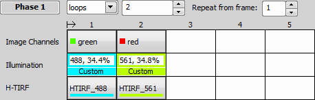
Figure 125. Example definition with two LAPP H-TIRF configurations
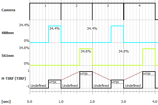
Figure 126. Oscilloscope view
Triggered Acquisition implementation
To use H-TIRF in Triggered Acquisition start by opening View > Acquisition Controls > Triggered Acquisition  and checking H-TIRF (TIRF) in the .
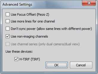
Figure 127. Settings dialog enabling H-TIRF
Set an Angle and Direction in the Ti-LApp H-TIRF Pad based on your experiment needs and create a new Optical Configuration for each setup. Up to four H-TIRF positions (Optical Configurations) can be created and used in Triggered Acquisition. Define your triggered experiment using the H-TIRF device selected in the Line column.
For more information about Triggered Acquisition, please see Triggered Acquisition.
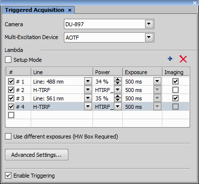
Figure 128. Triggered Acquisition example with H-TIRF
Warning
Camera cannot be in its overlap mode - the delay between expositions cannot be shorter than 5 ms.
Besides additional Magnification options the N-STORM controls are the same as in H-TIRF. Please read How to use LAPP H-TIRF for further information.
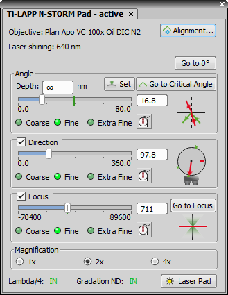
Figure 129. LAPP N-STORM Control Pad
Note
N-STORM alignment is always associated to a specific magnification.
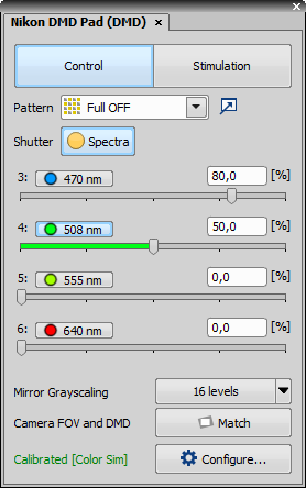
Figure 130.
Nikon DMD Pad controls the Nikon DMD module which enables multi-point photostimulation simultaneously in arbitrary areas and points of the sample. It consists of two logical sections – Control and Stimulation.
Control Section
Enables the user to choose one of the predefined patterns and user ROI/DMD patterns. Full ON/OFF turns the whole DMD area on/off. Grid displays a calibration grating – also used during calibration.
Pattern Manager is used for loading patterns from an image file (.bmp, .tiff, .tif, .stk, .lim, .png), organizing patterns, pattern mapping and metadata viewing.
To assign ROI(s) to a stimulation group (S1-S3), right-click over the ROI(s) in your image and select Use as Stimulation ROI: S1-3.
To save a pattern created on the current image with a calibrated DMD, right-click over your ROI(s) and select Export as DMD pattern.... Name your pattern file and specify where to save it. Once you click it is automatically added to the Pattern Manager and Pattern drop-down menu.
If the stimulation device is set as active ( Applications > 6D > Device for Stimulation: [Device Name]), ROIs with gray levels can be used. Specify the number of levels (see Mirror Grayscaling below) and define the gradient in the Intensity ROI Properties window evoked by right-clicking over the stimulation ROI(s).
Figure 131. Intensity ROI Properties dialog window
Use Constant Intensity to fill the whole ROI with a defined grayscale intensity level or switch to Gradient and choose its direction and extreme values. Once confirmed, information about the selected values is shown in the caption of the stimulation ROI.
Shutter This button behaves like a shutter. If it is turned on, the physical device turns the DMDs into position defined by the selected stimulation pattern.
Click on the arrow of the button and select the mirror grayscaling level suitable for your grayscale pattern. Then click on the button to activate the chosen grayscaling.
Note
Illumination sequence supports only the 1-bit level grayscaling mode (mirror grayscaling button needs to be unselected).
Match button matches the field of view of the camera with the DMD extent creating the largest camera ROI fully covered by the DMDs. All digital micro mirrors lying outside the camera FOV are turned off. If the camera FOV is larger than the DMD area and the camera chip is completely covered by the DMDs, the FOV is cropped to the largest horizontal rectangle covered by the DMDs. To maximize the stimulation area make the camera FOV parallel to the DMD area by manually rotating the mounted camera and clicking this button.
Configure... Opens the DMD Configuration dialog window used for selecting the HW Interface, associated devices, laser lines, switcher, shutters and for calibrating the DMD device. Calibration configurations highlight (red text) the microscope settings not matching the calibration.
If the device is not calibrated (red notification is displayed), start by clicking Configure... and choose one of the calibration methods. Auto Calibration is recommended – just follow the instructions in the Autocalibration dialog. Manual Calibration is suggested for advanced users. Calibrations can be deleted any time by clicking .
Inside the DMD Configuration window, select your HW Interface, Illumination device in the Light combo box, choose your laser lines, switcher, shutters and then click .
Note
It is currently not possible to use any Galvo XY device together with Nikon DMD.
Stimulation Section
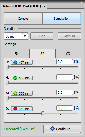
Figure 132.
Specifies the time duration during which the stimulation pattern is on.
This button activates sample stimulation using the selected stimulation group for the time period specified in the duration combo box. When the stimulation time runs out, the pattern is automatically turned off. If Toggle is selected in the duration combo box, this button works as a two position switch (on/off).
Turns on stimulation only when this button is pressed.
These tabs represent stimulation groups. Each stimulation group can contain many stimulation ROIs. Information about selected illumination lines and their illumination power is stored.
Illumination Sequence Interconnection
To be able to control Nikon DMD through Illumination Sequence (Illumination Sequence), you have to switch the HW Interface to USB/PCIe + Ext Trig in the DMD Configuration dialog inside the Device Manager ( Devices > Device Manager ).
Nikon DMD with other stimulation devices
Only one of scanning type stimulation device (including Confocal Galvano Scanner, MiniScanner and FRAPPA) and DMD device can be configured. Stimulation by scanning type stimulation device cannot be used when you add a DMD device (Nikon DMD, Andor Mosaic and Mightex Polygon 400) to the system. Please change the system configuration by removing the DMD device using Manage devices when scanning type stimulation device is required.
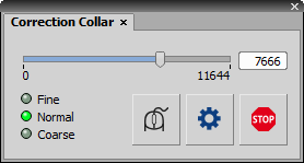
Figure 133.
This pad controls the Universal Motorized Aberration Correction device. Start by clicking the Axis Settings button and move the slider to find and set the Min/Max hardware range of the lens.
Micro-step position of the actuator. To fine-tune the position, hover the mouse cursor over the slider and use the mouse wheel or enter a precise value into the edit box.
This option changes the speed of the actuator when using the mouse wheel. Fine is the slowest speed and Coarse is the fastest.

Activates the mode where the mouse wheel rotation moves the actuator. The mouse cursor does not necessarily have to be over the slider.
Opens the Axis Settings dialog window where you can set the minimum (Min) and maximum (Max) position of the actuator or Reset the settings.
 Stop
Stop Immediately stops movement of the stage which can be used when there is a risk of collision.
(requires: Incubator NIS Special No.8)
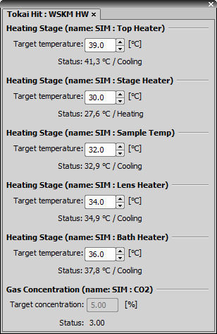
Figure 134.
This pad controls the Tokai Hit WSKM.
Control Panel Options
Each edit box enables the user to set the target temperature of the particular heater.
Enables the user to set the target gas concentration.
The CSU-W1 Pad controls the Yokogawa CSU-W1 spinning disk.
Control Panel Options
Select one of the two observation modes - Confocal/Widefield.
Specify the pinhole size.
Enter the disk speed [RPM] and click . Use the and buttons to fine-tune the disk speed.
Adjust the field aperture to confine laser illumination to the camera field of view.
This area controls all available filters. Clicking on opens the filter settings (see: View > Acquisition Controls > Filters, Shutters and Switchers  ).
).
Sets the relay lens position.
The CSU-X1 Pad controls the Yokogawa CSU-X1 spinning disk.
Control Panel Options
This button controls the CSU shutter.
Use the slider to adjust the speed of the spinning disk or enter speed [rpm] into the edit box and click to apply the settings. Use the and buttons to fine-tune the disk speed.
Area below the slider controls all available filters. Clicking on opens the filter settings (see: View > Acquisition Controls > Filters, Shutters and Switchers ).
Note
If you are using a CSU-X1 dual camera port model, go to Devices > Device Manager , click and check Dual Camera Model .