
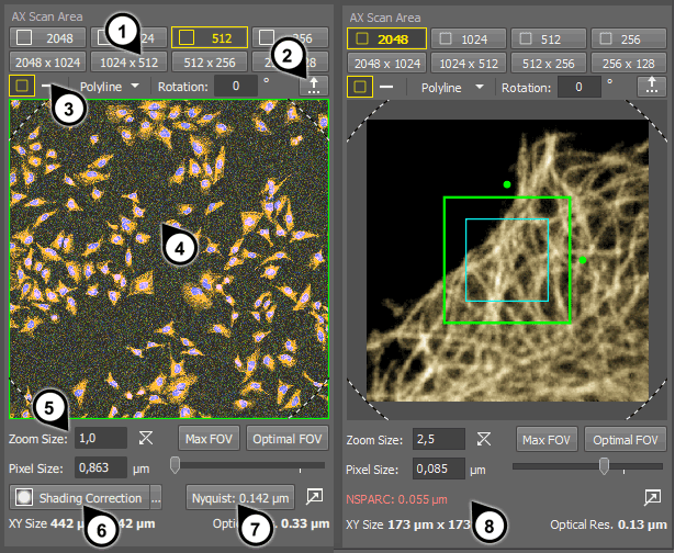
Figure 215. 1) AX Scan Area, 2) in NSPARC mode
Select pixel resolution of the image. There are the following options:
 , 2:1 rectangular area
 Different predefined sizes of rectangular areas can be selected by clicking on one of the buttons.
Use the  button to define oblong rectangular shapes or square shapes which are not represented by buttons on the
  AX Scan Area panel.
Any shape of the scan area can be specified. Select:
Square Scan Area A rectangular (strict square or oblong) scan area.
 Line Scan Area
 A linear (1DT) scan.
A polyline-shaped 1 DT scan. See Specifying a Polyline (1DT) Scan Area.
The Square Scan Area can be restricted by defining a ROI. See Specifying a ROI Scan Area.
The whole area of the panel represents the available FOV of the microscope. The currently active scan area is indicated by a green shape (rectangle, line, polyline). The shape can be moved or resized by mouse. In such case, it turns red and the change is only applied after you confirm it by right-click.
Tip
Zoom factor of the current scan area compared to full FOV.
Sets the scan area to match the full FOV.
Sets the scan area to a reduced FOV in order to suppress image shading by the borders caused by vignetting. Its size is indicated in the preview area by a dashed line.
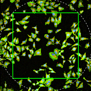
Figure 216. Scan area reduced to Optimal FOV
Note
The size of the optimal FOV depends on the actual hardware configuration. This button is hidden, if the configuration is optimal and the optimal FOV matches the maximal FOV.
An automatic shading correction can be applied to the image on thy fly. The correction image is calculated from objective parameters.
This button automatically adjusts zoom size or image resolution in order to achieve optimal pixel size. Its behavior can be changed in the settings dialog. The settings window can be opened by the  button. See Sampling.
(requires: NSPARC)
The optimal pixel size for the NSPARC detector is displayed below the current Pixel Size and the corresponding scan area (NSPARC FOV) is indicated in the preview as a cyan rectangle. The NSPARC pixel size is highlighted red if it is larger than NSPARC FOV. For optimal image resolution, set the pixel size equal or smaller than the suggested NSPARC value.
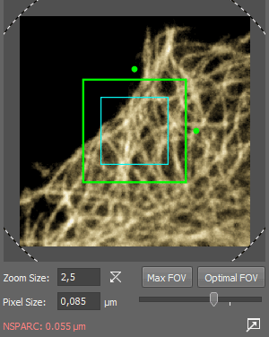
Figure 217. Scan area reduced in NSPARC mode
Note
The NSPARC FOV is calculated from the Nyquist resolution. In the multi-photon detector mode, it may be further reduced to assure the optical performance.
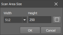
Figure 218. Definition of a custom rectangular area
Click the
button.Select Width from the pull-down menu. The available values are 64, 128, 256, 512, 1024, 2048, 4096 or 8192.
Type Height to the second editable field.
Tip
For a square shape, click the
button which will copy the Width to the Height field.The Keep Aspect Ratio option will disable the Height field and maintain the current aspect ratio if a different Width is selected.
Click to confirm the setting.
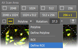
Figure 219.
Available only with the Galvano scanner.
Make sure the Live or Frozen image is displayed.
Reveal the pull-down menu in the
AX Scan Area panel and select the Define ROI command.A simple ROI editor appears over the image. Select a tool and draw one or more ROIs of any shape to the image. Confirm the definition by the Finish button.
The ROI will appear in the preview area and the button will be activated.
Once you run the Live image again, only the areas marked by the ROI(s) will be exposed to illumination.
Note
Scanning speed does not change, only the lasers turned off in the excluded areas.
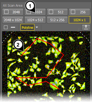
Figure 220. A finished but not yet activated polyline
Available only with the Galvano scanner.
The procedure of defining a ROI and a Polyline are similar (see above).
Start inserting node points of the polyline inside the preview area by the left mouse button.
Once the polyline ready, click anywhere in the preview area by the right mouse button to finish it. The right-clicked point will not be part of the polyline.
Right-click once more to the preview area (2) to activate the polyline for the live image.
Note
Image resolution (the set length of the line) can be changed by clicking on the square area preset buttons (1).
An automatic shading correction can be applied to the image on thy fly. The correction image is calculated from objective parameters.
Make sure the Show on AX Scan Area option is selected in the
 Configure window.
Click the button on the
AX Scan Area panel so it stays pressed. This activates the shading correction.Caution
If an objective is used which is not supported, a warning appears on the button. It means no shading correction is applied. When you select a supported objective on the nosepiece, the icon will disappear.
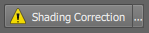
Figure 221. Warning - objective not supported
Display the live image (
 Live).
Click on the button and move the slider to adjust strength of the shading correction.