Run the  View > Image > ND View > Volume View
  command to display the current Z-stack as a 3D model using perspective projection.
There are the following rendering engines available in the software. If possible, select the Optimal renderer which is described primarily in the following sections. Display the  3D Settings window to select the renderer.
(requires: Optimal )
Click and drag directly in the volume image to freely rotate it.
Select a specific rotation mode in the side toolbar (Side Toolbar ).
Open the rotation panel found in the context menu of the
 Rotate around custom axis mode to rotate to basic planes or rotate using a precise orientation or rotation axis.
Click the
 Bounding box ( Bounding box) button.
Press the Ctrl key, place the cursor over one side of the 3D model (it gets red) and move the cutting plane. To drag two planes at once, move the corner ball.
Use the secondary mouse button to move the volume image within the screen.
Turn the mouse wheel to zoom the model in/out.
The basic workflow is this:
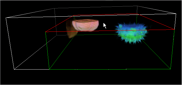
Figure 311.
Tip
Use the Ctrl + Shift + mouse button to move parallel cropping planes at the same time.
For more information about cropping and slicing please see: Crop & Slice.
Selects the dimension used for the volume viewing. If frame is selected, it can be chosen in the navigation bar below the image. Time projection is closely described here: Time-to-Volume Projection.

 First frame is highest,
 First frame is lowest
 Click the button to set the first frame as the highest/lowest one in the sequence.
Adjusts the Z-step height of the image Z sequence.
 Reset
Reset Z-zoom Resets the Z-zoom back to 100%.
Different rendering techniques can be used to display the Z sequence as a volume. Some combinations of the following techniques are available depending on which renderer is selected.
Uses the physical principles of light absorbing so that only the surface voxels are visible.
Alpha blending in combination with the Shaded Volume (see below).
Maximum Intensity Projection. Only voxels with the highest intensity in the observation direction are displayed.
Minimum Intensity Projection. Only voxels with the lowest intensity in the observation direction are displayed.
 Depth coding
 Turns on/off the volume color gradient perpendicular to the Z-stack planes. The lower part of the volume is colored with different colors than the top part based on the selected color gradient. It makes it easier to distinguish the object position within the whole Z sequence. Use the drop-down menu next to the icon to choose a gradient, Show depth code legend or Reverse gradient.

 Smooth volume
 Click on this button to show the volume smoothed or raw (non-interpolated).
 Edge Enhancement
 Turns the edge enhancement function on/off. This function reduces the opacity of the haze around the objects so that they are more contrasting and sharper. Open the context menu over the icon and move the slider of the selected channel to the right to increase the enhancement power.
 Full-res
 Low resolution is recommended for basic volume previewing. When precise static details are to be visualized, switch to high resolution (uses up to half of the available RAM). The most noticeable changes between these two modes are observed in large images (beyond the graphic card capabilities).
If the image is fully loaded into the memory of the graphics card, High resolution is turned on, the viewer shows the maximum quality and the button is automatically disabled. If the memory capabilities are exceeded, two more modes appear - Highest Possible Resolution (optimized for the highest resolution without downsampling; can be slower) and Balanced Resolution vs Speed (resolution can be lower; speed performance should be sufficient).
 Create Image Cache for Time Loop
 Use this button if your image sequence contains the time dimension and you would like to observe it. The visualization will be pre-loaded to memory and therefore smooth and fast enough.
 Full screen
 This option switches the volume viewer to full screen mode. You can abort this mode by pressing Esc.
Tip
When using two monitors, the Volume Options panel can be controlled from one monitor and the 3D volume can be in full screen on the other monitor.
 Snapshot
 Opens the Snapshot window where you can select the resolution and click to create a snapshot of the current volume scene in that resolution.
 Movie Maker
 This button runs the Movie Maker application. It enables the user to create AVI movies of the 3D model.
 Anaglyph
 This button turns on/off the anaglyph 3D view. Press the arrow next to the button to display the menu with possible color combinations (depending on the type of your anaglyph glasses).
 Open 3D settings
 Opens the 3D Settings window used for choosing a volume renderer and other 3D parameters. For details please see 3D Settings.
 Show volume view help
 Displays the help page.
(requires: Standard)
Select a rotation mode, e.g.
 Free Rotation, in the toolbar.
Drag the volume by the primary mouse button and rotate it.
Display the Volume Options (Standard renderer) panel.
Expand the View angle pull-down menu.
Define the position manually or click one of the predefined views.
Click the
 Show bounding box button.
Press the Ctrl key, place the cursor over one side of the 3D model (it gets red) and move the cutting plane.
(requires: Standard)
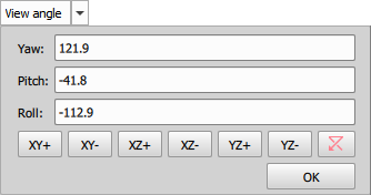
Figure 312.
Use the secondary mouse button to move the model within the screen.
Use the mouse wheel to zoom the model.
The basic workflow is this:
Figure 313.
Tip
Use the Ctrl + Shift + secondary mouse button to move parallel cropping planes at the same time.
Tip
(requires: Compatibility)
Or, you can enter the cropping mode by selecting the  tool. In this mode, you don't need to hold Ctrl for cropping.
See Cropping Tools .
Select the channel you will crop in the Channels section of the Volume Options (Standard renderer) panel and proceed with the cropping. With the Compatibility renderer, the “subvolume” buttons are on the right tool bar.
Hold Ctrl to select multiple channels.
Select between the cube and the axes via a context menu.
Click on an axis, a cube wall, or a cube corner to rotate the object so that it faces you.
Double-click to the volume view to reset it to the default position.
 Show Axis
 Show Grid
 Shows or hides the graticule. Define visible graticule planes in the Grid & Scale section of the Volume Options panel.
 Show Scale
 (requires: Standard), (requires: Optimal )
Displays/hides a scale around the bounding box.
 Show Z Scale
 (requires: Compatibility)
This button displays/hides the Z scale in the image window. Press the arrow button to open a menu with additional options.
 Show volume info
 (requires: Standard), (requires: Optimal )
Displays information about the calibration and volume dimensions at the bottom of the image window. It also displays the the navigation axes (or cube) to help you determine the current orientation of the volume.
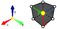
Figure 314. Navigation axis and navigation cube
Show volume dimensions (requires: Compatibility)
This button displays information about the calibration and volume dimensions at the bottom of the image window.
 Generate acceleration data file
 (requires: Optimal )
Generates the volume acceleration h5 file used for fast reloading of oversized volume datasets. Once the file is generated, the icon changes to  indicating that the file is recorded in the file manager (see below).
 Manage acceleration files
 (requires: Optimal )
Opens the Full-Res Acceleration Files dialog window managing all volume acceleration h5 files. Table with the files is sorted after clicking on the selected table header indicating the data order with a triangle icon. Use  to delete the selected file or use or .
 Show centroid instead of binary
 (requires: Compatibility)
Displays/hides a centroid for each binary object in the 3D image. Adjust the Centroid size in the nearby pull-down menu.
 Open Z-LUTs for Volume View
 (requires: Optimal )
Opens the Z-LUTs for Volume View panel (see: View > Visualization Controls > Z-LUTs for Volume View ).
 Calculate additional slices in Z axis for better quality (for highly undersampled datasets only)
 (requires: Compatibility)
This button enhances the quality of under-sampled datasets by calculating additional slices in the Z-axis.
 Create Image Cache for Time Loop
 Use this button if your image sequence contains the time dimension and you would like to observe it. The visualization will be pre-loaded to memory and therefore smooth and fast enough.
Switch to full screen mode rendering This option switches the volume viewer to fullscreen mode. You can abort this mode by pressing Esc.
Tip
(requires: Standard), (requires: Optimal )
When using two monitors, the Volume Options (Standard renderer) panel can be controlled from one monitor and the 3D Volume can be in full screen on the other monitor.
 Show Movie Maker
 This button runs the Movie Maker application. It enables the user to create AVI movies of the 3D model.
 Show Help
 Displays the help page.
When an image with a large volume dataset is opened, it generates a volume acceleration h5 file, which is then employed to quickly reload the volume datasets. Two icons appear on the main toolbar:
Generate acceleration data file (requires: Optimal )
Generates the volume acceleration h5 file used for fast reloading of oversized volume datasets. Once the file is generated, the icon changes to indicating that the file is recorded in the file manager (see below).
Manage acceleration files (requires: Optimal )
Opens the Full-Res Acceleration Files dialog window managing all volume acceleration h5 files. Table with the files is sorted after clicking on the selected table header indicating the data order with a triangle icon. Use to delete the selected file or use or .
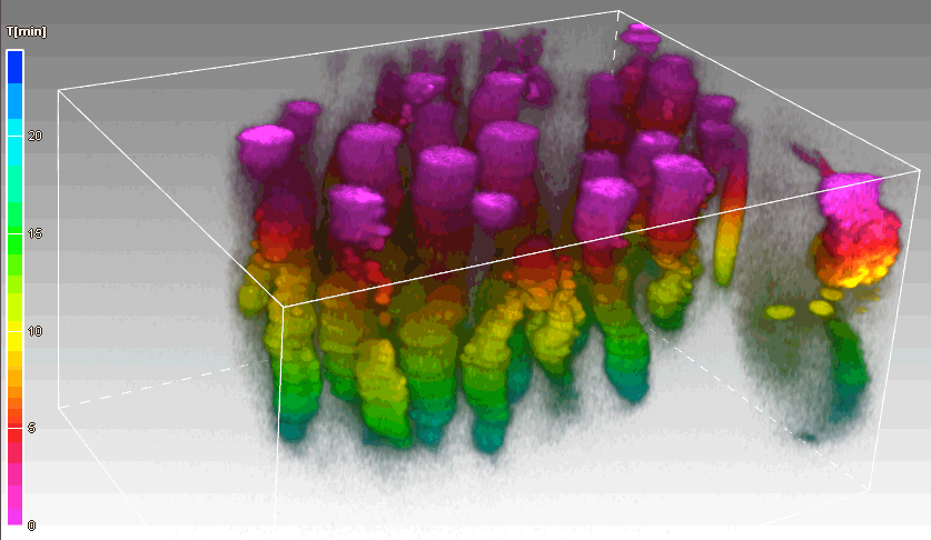
Figure 315. Timelapse displayed using the volume view
Timelapse images can be projected inside the volume viewer to illustrate time displacements. If more dimensions are available, select Time from the first drop-down menu in the Volume Options and choose a suitable blending mode. Click to set the first timelapse frame as the highest/lowest one in the sequence.
Note
For renderers other than Optimal, select the time dimension in the first combo box found in the top toolbar.
(requires: Optimal )
Open the context menu over the icon to switch between the navigation cube/axis and to turn on/off the additional information. Switching between the cube and the axis can also be done via the context menu revealed directly over the cube/axis (Set Orientation Marker to ...).
Click on an axis, a cube wall, or a cube corner to rotate the object so that it faces you.
Double-click to the volume view to reset it to the default position.
 Center view around picked point
 If you select this function or hold down Alt, clicking in the volume image automatically centers the view based on the clicked position.
 Pin rotation center to data center
 If turned on, the volume image is rotated from the center of the object. If turned off, the object rotates around the focal point based on the observer perspective.
 Rotate around object axis
 X Restricts rotation direction only to the X axis.
 Rotate around object axis
 Y Restricts rotation direction only to the Y axis.
 Rotate around object axis
 Z Restricts rotation direction only to the Z axis.
Rotate around custom axis Restricts rotation based on the values set in the Rotation axis (X, Y, Z) fields. Use the secondary mouse-click over the icon to reveal the window with shortcuts to the basic planes, Orientation settings (Yaw, Pitch, Roll) and Rotation axis settings. To make the window visible at all times, activate the  pin button.
 Volume info
 Displays information about the calibration and volume dimensions at the bottom of the image window. It also displays the Zoom info and the navigation cube (or axes) to help you determine the current orientation of the volume.
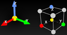
Figure 316. Navigation axis and navigation cube
 Show Grid
 Shows or hides the graticule. Define visible graticule planes in the Grid & Scale section of the Volume Options panel.
 Show Scale
 Displays/hides a scale around the bounding box. To adjust the scale parameters, reveal the context menu over the Bounding box icon. Details can be found here Displaying a Grid.
 3D measurement
 Measures distances inside the volume image. The View > Analysis Controls > Annotations and Measurements  panel will open with the
  Length 3D tool selected. When measuring centroids, the start/end of the measuring line automatically snaps to the center of the closest centroid.
Note
To measure distances more precisely, switch to Slices View ( View > Image > ND View > Slices View  ), make the measurement in the particular Z-plane, and switch back to Volume View.
 Crop/slice
 Turns the crop/slice mode on/off. Hold down Ctrl and move the desired plane with the left mouse button. The Crop/Slice panel, revealed by the secondary-mouse click over the icon, is closely described here: Crop & Slice.
 Binary
 Displays the binary layer of the 3D image. Use the key shortcut Ctrl + B.
 Color
Color Displays the color layer of the 3D image. Use the key shortcut Ctrl + R.
 Overlay
 Displays the color layer and the binary layer of the 3D image at once. Use the key shortcut Ctrl + V.
 Colorize by 3D Objects
 This function is used to distinguish between binary objects by colorizing each 3D object with a different color. This function can be turned on/off in the context menu over the 3D image where it is also possible to change the color of each binary 3D object (Change Binary 3D Object Color).
 Sync binaries with channels
 If a single channel is selected for display, only binary layers attached to it are displayed and vice versa. More information about attaching binary layers to channels can be found here: Attaching Binary Layers to Channels.
 Binary layers
 Opens the View > Analysis Controls > Binary Layers  panel.
 3D binary objects
 Opens the 3D Object Measurement tab displaying values of measured features for each 3D object in the image (see: Measure > 3D Object Measurement  ).
).
 Segmentation...
 Opens one of the thresholding methods to create 3D binaries from the current volume image:
(requires: Optimal )

Click this button on the image toolbar to display the Volume Options panel which contains the following options:
Image
Sets the opacity of the image. If a binary layer is present, it is left intact.

Resets the image opacity back to its default value.
The switch turns the edge enhancement function on/off. This function reduces the opacity of the haze around the objects so that they are more contrasting and sharper. Move the slider of the selected channel to the right to increase the enhancement power. Hold down Shift to move all active sliders at once. This function can be used only with Alpha and Alpha & Shade blending.
 XY,
XY,  XZ,
XZ,  YZ
YZ Displays maximum intensity projection images on the selected sides of the volume box. Select observation directions using the buttons (XY, XZ, XZ).
Crop & Slice
Cropping and slicing is turned off when this tab is selected.
Crops the image using an orthogonal ( ) or arbitrary (
 ) plane.
Box: Hold down Ctrl and move the mouse to select a plane. Then click and drag the plane while still holding Ctrl and release the mouse button to create the crop. To drag two planes at once, move the corner ball.
Plane: Hold down Ctrl and move the ball to set the center of the arbitrary crop. Then move the cone on the opposite end of the line to tilt the cropping plane. Release Ctrl to create the crop.
To reset any crop or cropping groups, click Reset. To create a new document from the current crop, click  Extract. Size of the crop is indicated at the bottom of the image window.
Cropping Groups
Both the channels (color squares) and the binary layers (color circles) can be independently cropped. Double-click on a channel (color square) or binary layer (color circle with the letter “B”) in this field or drag it into the  area to create a new cropping group (a new row is created). Crop is then performed only on the selected cropping group.
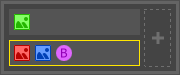
Figure 317. Example of two cropping groups (rows). The second group with two channels and one binary layer is active (crop is applied on this group).
Multiple slices can be created in the image either manually or automatically. Click on a slicing plane ( XY, XZ, YZ), hold down Ctrl, click on the plane and move it to position the slice. A row record is added to the table below where it can be  shown,
  hidden or deleted.
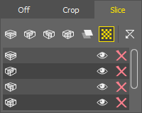
Figure 318. Slice tab.
When working with the  Free slice, hold down Ctrl and move the ball indicator to set the center of the slicing plane. Then move the cone indicator on the opposite end of the line to tilt the slicing plane. Release Ctrl to create the slice. To recognize the slice(s) position better, turn on the slice
  Transparency. To remove all slices from the image, click Reset.
To calculate the slices automatically, click Auto.... The Auto slices window opens:
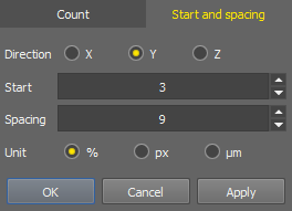
Figure 319.
Slices are generated either by the number of slices (Count tab - set the direction axis or time and the number of slices) or using a spacing value (Start and spacing tab - set the direction axis or time, the start position and spacing using the selected units). Click to see the calculated result, then for confirming the settings and closing the window.
Binary
The slider sets the opacity of the binary layer.
Hides the binary front faces so that the inside of the binary volume is more visible.
Use the slider to adjusts the thickness of the mesh line.
Sets density of the triangular mesh.
Remeshing adjusts the grid to the most regular equilateral triangles. Uniform remeshing makes all triangles the same size; it adaptively adjusts the size of the triangles and thus the density of the mesh according to the local complexity of the shape. Adaptive remeshing has a minimum triangle size the same as uniform, so it is allowed to reduce the grid density on large simple areas, but does not densify around details. This is because the mesh is mainly used to achieve binary transparency, so that a dense, opaque mesh does not form around fine details.
Use the slider to adjust the size of the binary centroid(s).
Detailed description can be found here: Displaying a Grid.
Tip
Each section of the Volume Options panel can be collapsed/expanded using the 
 buttons.
(requires: Standard)
Note
If you use the Compatibility renderer, these tools are placed on the right image tool bar, otherwise in the Volume Options (Standard renderer) panel.
 Volume Options
Click this button on the image toolbar to display the Volume Options (Standard renderer) panel which contains the following options:


 , Rotation around the selected axis
 Restricts rotation direction only to the selected object axis.
 User-defined rotation axis
 Rotate the model around a user-defined axis. Click the arrow to display a context menu where you shall define coordinates of the second point of the axis. The first point is the origin of the 3D model.
Display the pull-down menu in the top image tool bar and select which plane will be facing you from the six predefined views (side views and horizontal projections). The Default view is slightly rotated so that the structure of the sample can be overviewed.
Defines the 3D image rotation using three values (Yaw, Pitch, Roll). Or you can select a predefined plane as in the View Plane menu.
Adjusts the Z-step height of the image Z sequence.
 The first frame is highest,
  The first frame is lowest
 Use these two buttons to set the first frame as the highest/lowest one in the sequence.
Different rendering techniques can be used to display the Z sequence as a volume. Some combinations of the following techniques are available depending on which renderer is selected.
Uses the physical principles of light absorbing so that only the surface voxels are visible.
Alpha blending in combination with the Shaded Volume (see below).
Only voxels with the highest intensity in the observation direction are displayed.
Only voxels with the lowest intensity in the observation direction are displayed.
Accumulates voxel intensities in the observation direction. The result is often over-saturated, therefore you can adjust the display intensity in the 3D Settings window.
A gradient selected in the nearby pull-down menu is used to colorize the volume.
(requires: Standard)
Uses the physical principles of light absorbing and reflectance. The object surface becomes more distinguishable.
 Full-res
 Low resolution is recommended for basic volume previewing. When precise static details are to be visualized, switch to high resolution (uses up to half of the available RAM). The most noticeable changes between these two modes are observed in large images (beyond the graphic card capabilities).
If the image is fully loaded into the memory of the graphics card, High resolution is turned on, the viewer shows the maximum quality and the button is automatically disabled. If the memory capabilities are exceeded, two more modes appear - Highest Possible Resolution (optimized for the highest resolution without downsampling; can be slower) and Balanced Resolution vs Speed (resolution can be lower; speed performance should be sufficient).
 Show smooth volume
 Click on this button to smooth the 3D volume.
 Show non-interpolated volume
 Click on this button to display raw, non-interpolated 3D volume.
 Anaglyph 3D stereo (left / right eye)
 This button enables/disables the anaglyph 3D view. Press the arrow next to the button to display the menu with possible color combinations (depending on the type of your anaglyph glasses).
 Toggle light visibility
 (requires: Standard) (requires: Compatibility)
Press the button to switch the light on. Move the light freely around using the left mouse button. Double-click on the light to pin it to the scene (stays in its place, 3D volume moves) or to the volume (light moves together with the 3D volume). Change the light intensity with the mouse wheel when the cursor is over the light. Context menu over the light can be used to Reset Light Settings.
Enable Edge Enhancement, Disable Edge Enhancement (requires: Standard) (requires: Optimal )
Turns the edge enhancement function on/off. This function reduces the opacity of the haze around the objects so that they are more contrasting and sharper. Move the slider of the selected channel to the right to increase the enhancement power.
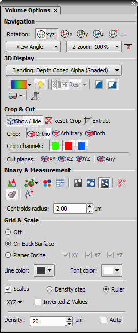
Figure 320. Volume Options.
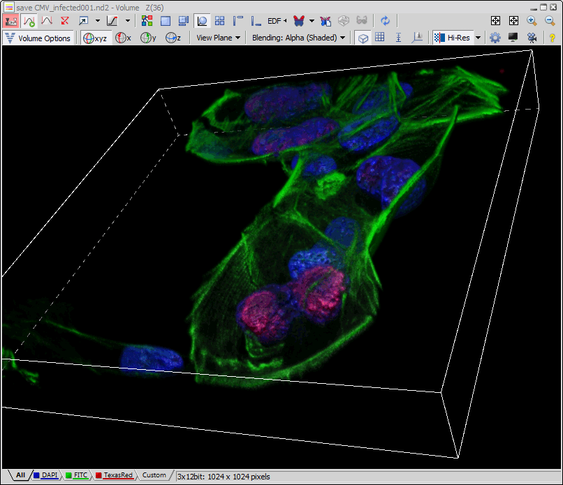
Figure 321. Volume view window showing the standard renderer with main toolbar controls.
Grid and Scale (Optimal renderer)
(requires: Optimal )
Grid Grid is activated in the right toolbar. Parameters of the grid can be adjusted in the window revealed by a secondary-mouse click over the  icon or in the Volume Options.
Grid can be set to Back, showing the grid on the bottom and far sides of the volume, or to where the grid position is adjusted by holding Shift and clicking and moving the grid plane. User can set which grid planes are shown by clicking on the buttons (, , ). Grid density can be set automatically (Auto switch on) or specified manually in the edit box.
Colors of the bounding box, grid line and scale axes are set below after clicking on the squares. When you hover over a square, a tool tip shows which element the color will be assigned to. To reset the colors back to default, click .
Scale Scale is activated in the right toolbar. Its parameters can be adjusted in the window revealed by a secondary-mouse click over the Bounding box icon or in the Volume Options.
Scale: Outside adds a scale ruler to the outside of the bounding box. Scale: Center adds a scale ruler into the center of the bounding box. Scale: Focus locks the scale ruler in the center of the image window. Only the dimensions selected using the three axis buttons (X, Y, Z) are shown.
Grid and Scale (Standard renderer)
(requires: Standard)
If switched on, grids are shown in the volume view.
Shows a grid on the bottom and distant sides of your current volume view.
Displays/hides the XY, YZ, and XZ planes (use the toggle switches). Each plane is carrying an automatic or manually defined grid. Hold down Shift to evoke a small cube. Drag the yellow ball of the cube to alter the zero grid position. Drag the arrow ends to move the grid just in the selected axis direction.
If switched on, a labeled scale is shown in the volume view.
Shows a labeled ruler on the edge of the prism marking each grid line with its distance from 0.
Shows a labeled scale aligned with the volume view axis or with the screen.
Defines which axes are labeled when Ruler is selected.
Changes the direction of the Z ruler.
Adjusts the density of the grid or scale if Auto is switched to off.
Automatically calculates a suitable spacing of the grid and the scale.
Changes the color of the grid/plane line.
Changes the color of the grid/scale and its labels.
Grid (Compatibility renderer)
(requires: Compatibility)
The grid is called Graticules in the Compatibility renderer. Click the Show Grid button in the image tool bar to display it. Reveal the pull-down menu of the button to display the following options.
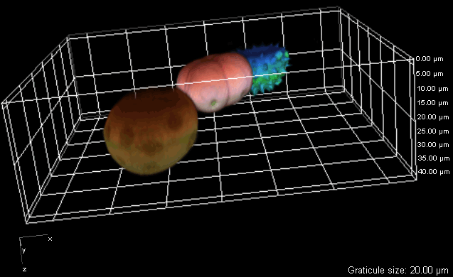
Figure 322. Graticule Visibility - Halved bounding box (on bottom)
Select which planes will contain the graticule.
Displays the grid on all sides of the box displayed behind the volume. With the Always on Top option selected, it is the contrary.
Displays the grid on three sides of the box. With the Always on Top option selected, the opposite sides of the box are used.
Displays a window with graticule settings.
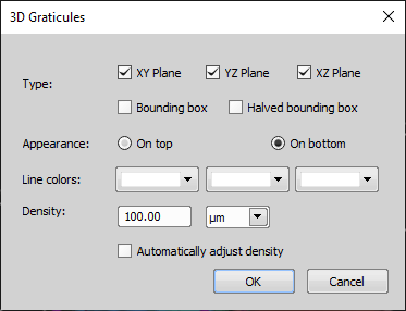
Figure 323. Graticule Properties Window
Select which planes will be visible. You can combine them with other planes. Check the Bounding Box option to show the graticules on all sides of the box. The Halved bounding box displays graticules on three sides of the box.
Adjust the graticule visibility. The graticule can be shown at the top or in the background.
Select a color for each axis individually.
Specify value and units of graticule density. Check the Automatically adjust density option to let the system set the graticule density automatically. The information about the current graticule size is displayed in the bottom right corner of the image window.
Moving the graticule
(requires: Compatibility)
To move the graticule freely, hold down the Shift key, grab the graticule and drag it to a new position. If you need to adjust the graticule position only in some directions, hold down the Shift key. An axis system scheme appears. Point the mouse cursor on one of the axes or planes you want to fix. The selected plane (or axis) becomes highlighted. Now hold the primary mouse button and move the mouse cursor. The graticule will move accordingly in the selected plane or axis direction.
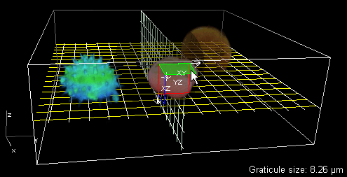
Figure 324. The XY plane is selected so the graticules will move only in the X and Y axis direction
(requires: Standard)
 Define 3D Threshold
 Opens the 3D threshold window used for segmentation of 3D objects.
 Spot Detection 3D
 Detects bright/dark circular objects within a 3D space. Please see: Spot Detection for more information.
 Colorize Binary by 3D Objects
 This function is used to distinguish between binary objects by colorizing each 3D object with a different color. This function can be turned on/off in the context menu over the 3D image where it is also possible to change the color of each binary 3D object (Change Binary 3D Object Color).
3D Object Measurement Opens the 3D Object Measurement tab displaying values of measured features for each 3D object in the image (see: Measure > 3D Object Measurement ).
View Binary Displays the binary layer of the 3D image. Use the key shortcut Ctrl + B.
 View Color
 Displays the color layer of the 3D image. Use the key shortcut Ctrl + R.
 View Overlay
 Displays the color layer and the binary layer of the 3D image at once. Use the key shortcut Ctrl + V.
 Open Binary Toolbar
 Opens the Binary Toolbar ( View > Analysis Controls > Binary Toolbar ).
Show/hide centroids Displays/hides a centroid for each binary object in the 3D image. Adjust the Centroid size in the combo box in the dialog window.
 3D Manual Measurement
 Measures distances inside the 3D image. The View > Analysis Controls > Annotations and Measurements panel will open with the Length 3D tool selected. When measuring centroids, the start/end of the measuring line automatically snaps to the center of the closest centroid.
Note
To measure distances more precisely, switch to Slices View ( View > Image > ND View > Slices View ), make the measurement in the particular Z-plane, and switch back to Volume View.
(requires: Standard)
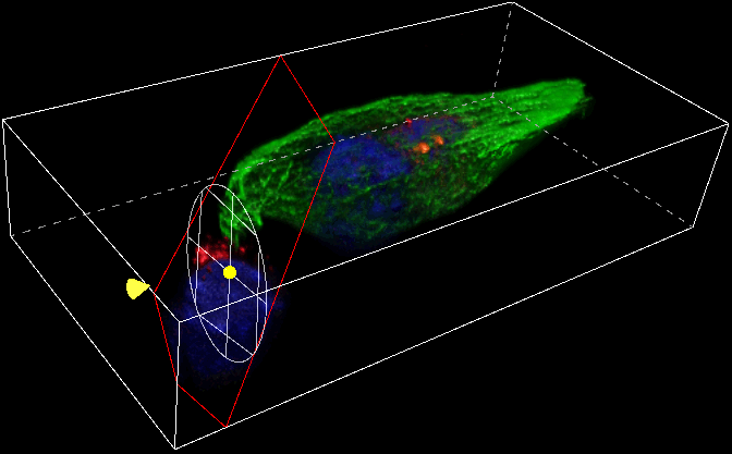
Figure 325. Cropping using both orthogonal and arbitrary crops
Display the Volume Options panel which contains the following tools:
Show/Hide Displays or hides any cropping and cutting made on the 3D image.
 Reset Crop
 Removes any crop changes made on the image and returns the cut planes into their default position.
Extract Extracts a new document from the current view limited by the crop/cut tools.
Ortho This mode crops the 3D image perpendicularly. Hold down Ctrl and move the desired plane with the left mouse button.
 Arbitrary
 This mode crops the 3D image freely. Hold down Ctrl and move the yellow ball to position the center of the cropping plane and then move the yellow cone to tilt the plane which is illustrated by the white circular grid.
 Both
Both Both orthogonal and arbitrary crops are enabled at the same time (see above).
Note
If you restrict the volume size using the cropping tools, you can shift the result inside the original volume in all three directions. Press Ctrl + Shift and then click and drag over a plane determining the shift direction. Color lines with crosses indicate the shift axis.
 XY,
XY,  XZ,
XZ,  YZ
YZ A plane delimited by two axes can be used for cutting through the 3D image. Hold down Ctrl and drag the cutting plane in the direction of the remaining axis.
 Any
Any Any plane can be used to cut through the 3D image. Hold down Ctrl and move the yellow ball to position the center of the cutting plane and then move the yellow cone to tilt the plane.
Select which channels will be cropped. This option is available only with Ortho cropping.
Click the 3D Settings button on the image toolbar to adjust the settings of the volume renderer.
3D Settings (Optimal Renderer)
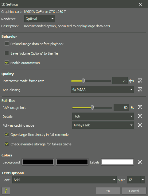
Figure 326.
Data are preloaded automatically before each playback of a time dimension. If not selected, smoother playback of volume images containing the time dimension can be provided by clicking on the Create image cache for time loop button.
Saves individual settings of each image (view angle, crop, etc.) to the image file.
If checked, the manually spun volume will continue spinning.
is used to adjust the optimal frame rate used when moving the 3D model.
Anti-aliasing is used to smooth the edges of the lines to minimize the distortion artifacts when representing a high-resolution volume at a lower resolution.
Set conditions for activation of the Full-res button.
Sets how much of the RAM memory can the full-res mode use. For optimal running, it is best to keep as much of the document ready in RAM as possible, but please keep in mind that the system and other processes within NIS-Elements also need some memory to run.
Sets the quality of displaying images. The level of detail in full-res varies according to the current view angle and especially the zoom factor. This factor determines how “pixelated” the data can be. In practice, this means that at a value of 1 the highest quality will be preferred. At a value of 5, you will need to zoom in for detail, but the smaller data volume will make the viewing much faster.
Sets how to handle preloading of oversized datasets.
The user is prompted every time there is a need to generate the acceleration file.
Only portions of the dataset which are needed for the current view load automatically. It displays the image faster than the Preload option at first, but it subsequent manipulation is slower.
Always preloads the whole dataset. It takes some time when the image is opened, but all subsequent actions are fast.
If volumetric data exceeds the available RAM, the Full-res button in the Volume Options panel will be enabled and pressed automatically.
Full-res (for oversized datasets) loads data in smaller blocks and uses cache (auxiliary *.h5 file) for faster reloading. If this check box is selected, the space available for this cache is verified when the document is opened.
By clicking on these color rectangles you can define the background color and color of the labels. A background gradient can be defined by selecting two different background colors. Click on the button to set all colors to their default values.
These options influence the axes displayed around the bounding box and other texts displayed in the Volume Viewer (Zoom, Size, Calibration).
Sets the text font type.
Sets the size of the text.
Help Opens this help page.
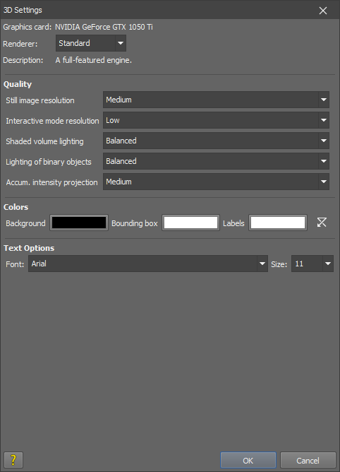
Figure 327.
Switches between the engines. Options change based on the selected engine.
This resolution is used for static viewing (which usually allows the highest quality).
This resolution is used when moving with the 3D model.
Choose one of the lighting modes.
Lighting presets are available in this combo box. Illumination is adapted according to the selected binary surface. Balanced mode automatically balances light irrespective of the surface type.
Modifies (multiplies by a coefficient) the pixel intensity sums created by the AccumulatedIP blending mode.
By clicking on these color rectangles you can define the background color, bounding box color, and color of the labels. Click to set all colors to their default values.
These options influence the axes displayed around the bounding box and other texts displayed in the Volume Viewer (Zoom, Size, Calibration).
Sets the text font type.
Sets the size of the text.
Help Opens this help page.
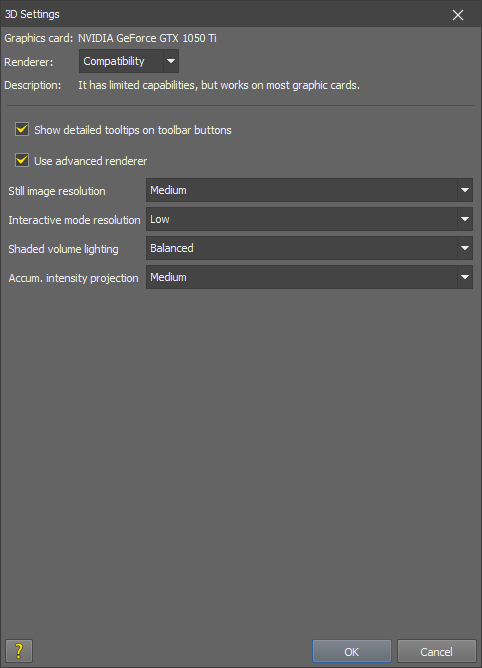
Figure 328.
Note
The 3D Settings button only if you have a high-performance graphic card with DirectX 9.0c support, Shader Model 3.0.
Check this item to display detailed tool tips.
If an advanced graphic card is detected in your computer, this option becomes available. Choose it to make use of the extra capabilities of the card. The resulting image will be nicer and the performance faster.
Note
If this option is turned off, a stripe pattern may appear in the volume render.
This resolution is used for static viewing (which usually allows the highest quality).
This resolution is used when moving with the 3D model.
Choose one of the lighting modes: Balanced, Matte, or Shiny.
Select the intensity of accumulating the pixel values: High, Medium, or Low.
Help Opens this help page.