
(requires: Analog IO device)
This special option in ND acquisition controls the experiment from outside (section When Device Changes Then Do Action) and also allows the experiment to give feedback (section On Experiment Event Set Device Output). A special device (NIDAQ controller set) is required to run this option.
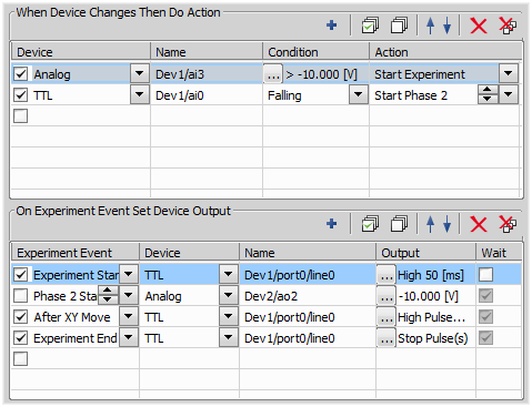
Figure 290. Input/Output Example
An example of an input: When voltage in dev1/ai3 line of an analog input is higher than -10 V, then the experiment starts.
An example of an output: When experiment starts, a high TTL type of signal which lasts 50 ms is given through Dev1/port0/line0 line.
When Device Changes Then Do Action (Input) options
Type of used device. Available selection of devices depends on NIDAQ Input configuration.
Displays name of the used NIDAQ device line. If more than one line is defined then the other ones can be selected from the list.
Specify conditions that should be met to create an event - e.g. when the voltage reaches some level (analog input) or the TTL signal changes. For TTL signals, just choose whether to produce the event upon the rising or the falling edge. For analog input type, press the button and define the range of voltages to fulfill the condition.
Conditions dialog
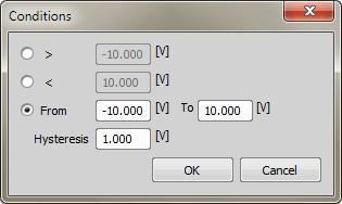
Figure 291.
Define condition as output of a TTL line bigger/smaller then corresponding value, or in a certain range. The hysteresis parameter defines a lag between the moment the condition is actually fulfilled and the moment the specified event takes place. It works this way:
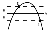
Figure 292. Voltage curve
Voltage value whose reaching shall create an event
Hysteresis setting in volts
Moments when the event actually takes place.
Select which event is performed when the Conditions are fulfilled (i.e. the signal is sent). You can choose either that the experiment starts, ends, moves to next phase or any other phase, or you can use one of the user defined actions. Use the arrows to define exactly which phase or user event is used.
Real-time TTL inputs
When a RealTime TTL Input is defined in NIDAQ configuration, status changes of the TTL line are recorded automatically during ND experiments and can be later displayed within the Recorded Data section of the  File > Image Properties command. Within this window, the Recorded TTL data can be converted to User Events - which are visualized on the ND document time scale.
Note
This feature is supported only by cards with combined PFI and standard TTL inputs (e.g. NI M-series cards).
On Experiment Event Set Device Output options
Select which event triggers defined output signal. You can choose the event from the pull down menu. Use the arrows to define exactly which phase or user event is used.
Type of used device. Available selection of devices depends on NIDAQ Input configuration.
Displays name of the used NIDAQ device line. If more than one line is defined then the other ones can be selected from the list.
Specify values of the generated signal. Set conditions for TTL type of signal in the dialog window that appears when you press the ... button:
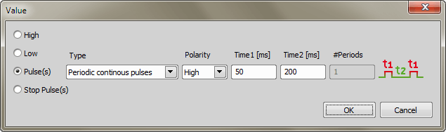
Figure 293.
The generated signal can be High, Low, or in a form of a Pulse lasting for defined time interval. You can define type, polarity and time characteristics of the pulse. The Stop Pulse(s) defines value of NIDAQ TTL line recognized as the stop pulse.
For analog signals choose the proper voltage Value:
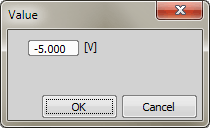
Figure 294.
This option is enabled only for TTL pulses or Incubator, if connected. If checked, the experiment runs after the pulse ends (experiment waits on the selected event for defined output setting and afterwards continues). If left unchecked, the experiment does not wait for the end of the pulse (defined output settings on the selected event) and runs regardless of the current output.