
(requires: Stage XY axis)
This window serves for defining XY(Z) points to be scanned during the multipoint capture experiment. This feature is available when a motorized stage XY(Z) is present in the system. Check the Include Z box to display the Z column. The list of defined points can be saved (and loaded later) to an XML file by the Save (Load) button. Run the  Acquire > Capture Multipoint > Capture Automatically command.
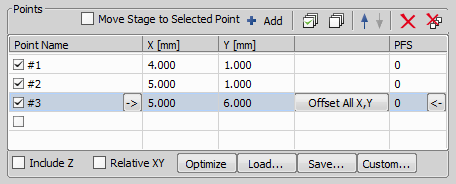
Figure 278.

You can insert a pattern designed to cover a wellplate. Of course it can be used to create any rectangular pattern.
Click the button. The following window appears
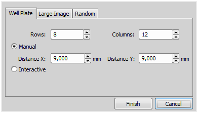
Figure 279.
Select Manual if you know the distances between wells. Otherwise select the Interactive and continue.
ManualThis method will create a pattern which will scan Rows x Columns fields. The Distance X and Y parameters specify distances between two fields. The scanning will begin at the current position.
InteractiveThe interactive method lets you specify the number of fields to be scanned and starts a wizard where you will specify the top-left and the bottom-right corner of the well plate. The distances between wells are calculated automatically.
Click .
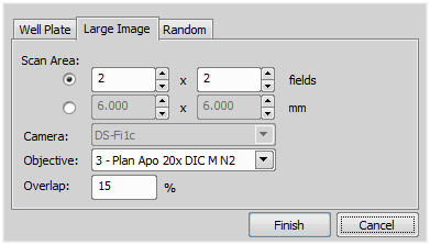
A Multi-point which will cover certain area can be created:
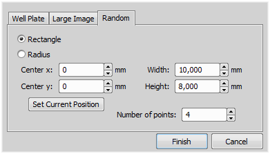
Specify the area where a random set of points will be generated.
Note
The XY coordinates of one point cannot be adjusted (unless you delete it and add a new point).
Make sure the Move stage to selected point is pressed. This button ensures that the motorized stage moves to the coordinates of the currently selected point.
Select one point of the list.
Move the XY(Z) stage to a new position (define the offset).
The coordinates of all points change - the same shift which you made with the stage is applied to them.
The button can shift the XY coordinates of all points in the same way:
This button ensures that the motorized stage moves to the coordinates of the currently selected point.
Displays the name of the point. You can change the name (default names are #1, #2 #3, etc.).
Displays X, Y and Z coordinates of the point. The arrow buttons assign the current XYZ position to the point. The button shifts the XYZ coordinates of all points by the same offset which is defined as a difference between the current stage coordinates and coordinates of the selected point.
If checked, Laser Power Settings dialog window appears when defining stimulation ROIs. This window defines the power of each laser line on each stimulation group.
Check the Relative XY item to consider all coordinates as relative with respect to the current stage position. Any of the points may be used as the reference point, just right-click it and select Set this point as a reference position.
If the Optimize button is pressed, the system will re-order the defined points in order to minimize the XY stage trajectory.
Displays a tool for creating predefined multi-point patterns.
See Well Plate (Rectangular) Multi-Point, Large Image (Covering) Multi-Point, Random Multi-Point.
Check this option to redefine reference Z position after performing autofocus or PFS (if AF or PFS is turned on).
Select this box to perform the File > Import/Export > Split Multipoints command directly after the ND2 experiment.
Note
When you apply the Split Multipoints command on ND acquisition that contains only the XY dimension, the information about the ND dimensions in the File > Open  dialog becomes unavailable.