
The following image layers can be saved within a NIS-Elements image.
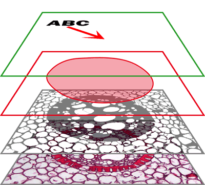
Figure 315.
In this layer, vector objects are stored. The results of manual and automatic measurements, text labels and other annotations can be included.
The binary layer is usually the result of segmentation. By segmentation, you distinguish objects of interest from background. A picture of night sky can make a nice example - shining stars may be “thresholded” and compose a binary layer. Then, by means of automatic measurement, you can count them. More than one binary layer can be placed over one image. See Binary Layers.
ROIs (regions of interest) is a strong tool for distinguishing objects from background similar to the binary layer. The advantage over the binary layer is that ROIs are vector objects and therefore provide different way of manipulation. See Introduction to ROIs.
The color layer contains the image data captured by a camera. It can handle images with the depth of up to 16 bits per color component. The dimensions of this layer determines the dimensions of the other layers.
Note
When saving an image, only some file formats are capable of saving all the layers. The other image formats will save the content of the color layer only. See Supported File Formats.
RGB Images
Images acquired by a color camera typically consist of three components that represent red, green and blue channel intensities. You can display a single color channel using the tabs located in the bottom-left corner of the image window. Or, an arbitrary combination of them can be selected while holding the Ctrl key down.

Figure 316.
Multi-channel Images
These documents usually arise from fluorescence microscopy. Instead of 3 color components (RGB), multichannel images can be composed of arbitrary number of user-definable color channels.
Note
If an image contains more than 8 components, the tabs in the bottom left corner of the image are replaced by the wavelength dimension, similarly to how other dimension loops of ND2 files are displayed.
Click the  Treat As Spectral button in the top image toolbar to use the current image as a spectral image revealing more channel switching features in the bottom control bar.

Figure 317.
Selects the full spectrum of the image including spectral (FLUO) and transmitted detector (TD) channels.
Selects only spectral channels. This button is useful for quick switching between FLUO and TD.
Displays only the transmitted detector (TD) image.
This button displays custom channels. To set a channel (multiple channels) as custom, make a channel selection in the control bar, right-click over the selection and choose Set selected channels as Custom.
Alternatively switch to the  Split Components view, select multiple channel thumbnails and choose Set selected channels as Custom from the context menu over the image. Then select Show Thumbnail of Merged All Channels to include the All channels thumbnail or Show Thumbnail of Merged Custom Channels to include the Custom channel thumbnail.
Equation Channel Images
(requires: Calcium, FRET)
When processing image channels using custom equations ( Applications > Ratio, Ca2+, FRET > Add New Equation View or Applications > Ratio, Ca2+, FRET > Add New Equation View on Live), new Equation channels are created. These channels represent a combination of the source image channels and mathematical functions. A real image channel can be created from an equation channel after secondary-mouse clicking on the Equation channel tab and selecting Convert Equation to Mono Channel or Convert Equation to Floating Point Channel. The equation channel can also be exported to an RGB image (Extract as RGB Snapshot) or as a floating point image (Extract as Floating Point Image).
ND2 (multi-dimensional) files / datasets
An ND2 file is usually a sequence of images. One ND2 file can contain multiple images organized according to what type of acquisition they came from. There are the following acquisition types, also called dimensions available: Time-lapse, Multi-point, Z-series, Multi-channel, Large-image. The dimensions can be combined together.
Please see Navigation in ND2 Files, About ND Acquisition.
Single channels and monochromatic images can be visualized using a predefined color scale. Right-click the “channel tab” in the bottom left corner of the image window and select a color scale from the  Channel Coloring... sub-menu.
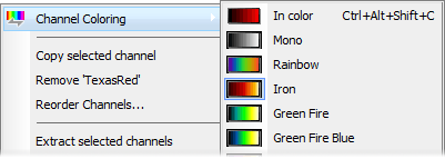
Figure 318.
Brightfield and Fluorescence channel image
If your ND2 image contains only one Brightfield channel with its Modality set to Brightfield in Channel Properties, the behavior of viewing colors of these channels slightly changes. The Brightfield channel is set to Mono color by default but can be switched to any other pseudocolor. The fluorescence channels are displayed in their native fluorescence color by default and can by switched to any other pseudocolor. Once the Brightfield and fluorescence channels are displayed together in an overlay, the pseudocolor of the fluorescence channel is ignored and is shown in its true color.
Despite the color in which a channel is displayed, other per-channel colors can be assigned to it. This regards colors for:
indication of oversaturated pixels
indication of undersaturated pixels
indication of binary pixels
In the context menu over a channel, select  Colors for '
channel name' and choose a color for oversaturated pixels, undersaturated pixels (these colors are used globally for all images in NIS-Elements until next change) and for binary pixels. Selected color for binary pixels is linked to the channel name and is shown in all images having the same channel name.
Figure 319.
Color of oversaturated and undersaturated pixels may also be selected from the pull down menu next to the Pixel Saturation Indication (Ctrl+Shift+S)  button shown in the image toolbar.
Figure 320. Pixel Saturation Indication sub-menu
The pixel saturation will not be indicated.
Color which has been previously assigned to oversaturated and undersaturated pixels in the menu over the channel tab will be used. See Assigning Colors to Channels.
Colors complementary to the display color of each channel will be used in order to ensure good visibility of the highlighted pixels.
Drag one of the channel tabs and drop it:
Figure 321.
to another image, so it will become a multichannel image;
inside the NIS-Elements application window in order to create a new image
Note
When extracting a channel from Live image, it does not freeze the camera signal.
Any user events (Events) present in the document are automatically transferred during the channel extraction.
ND2 files
Drag one of the channel tabs and drop it by the primary mouse button. It behaves the same way as if performed on a single image.
Drag one of the channel tabs by the secondary mouse button and drop it to the application screen. A context menu appears that enables you to select whether to create the new image from all frames or just a single frame.
Two ND2 files that have matching structure can be merged into one easily. E.g. two single channel Z stacks with the same number of Z positions can be merged into a single two component ND2 Z-stack by dragging one into the other.
Drag one of the channel tabs of a single image and drop it to an ND2 file. The channel will be copied to every loop of the ND2 file.
Note
This behavior, too, takes place when copying channels that do not have matching structure (just the current frame is copied to every position of the target ND2).
The currently selected channel(s) can be shifted using the CTRL + SHIFT + Arrow keys. All channels are visible during the operation so you can see the complete image.
The procedure also works on ND2 files equally to other image processing performed on ND2 files:
Select the image frame and the channels to be shifted.
Perform the shift using Ctrl+Shift+Arrows keys.
A standard ND2 image processing window appears (see ND2 Files Processing).
Select which part of the ND2 file to apply the shift to, and confirm it by .