Click the  Exp. Settings button on the
  Experiment tool bar display the following window. There you can create and adjust presets which can be then quickly selected from a pull-down.
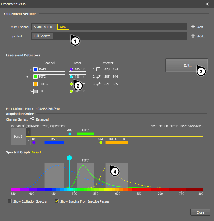
Figure 162.
You can create a preset either by clicking the button on the right or by duplicating an existing preset via a context menu.
A scheme of the currently selected lasers, detectors, and their mutual assignment.
Click the button to enter the edit mode. In this mode, channels can be ordered, lasers can be removed or assigned to different detectors, etc. See Editing a Multichannel Preset in Expert Mode.
A graph where laser wavelengths, filter ranges, dye emission and excitation spectra of the current preset are indicated. The acquisition order of channels is indicated at the bottom.
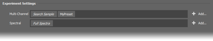
Figure 163. Experiment settings of the AX configuration
In this section, experiment presets can be created, duplicated, renamed, deleted, etc. Click the  Add... button to open a dialog window where the selected type of preset can be created.
Presets are sorted to categories, only categories valid for the currently selected light path are displayed.
Visible lasers and the DUX detectors are used.
(requires: DUX-VB)
Visible lasers and one DUX variable filter detector is used. Spectral (continuous bandpass) images can be acquired with this kind of preset. A wavelength range is set by the user and it is scanned step by step while moving the filter range.
(requires: AX MP) and (requires: NSPARC)
MP NSPARC IR laser and the NSPARC detector are used.
IR laser(s) and DUX detectors are used.
(requires: DUX-VB)
IR laser(s) and one DUX detector are used.
See Creating a Multiphoton Experiment Preset - DUX Spectral Detection.
IR laser(s) and the NDD detector are used.
See Creating a Multiphoton Experiment Preset - NDD Detection.
Tip
The order of user-created presets which is also applied in the pull-down menu of the AX Pad panel can changed by moving the preset name by mouse.
Automatic Presets
There are the following presets which are created automatically.
An optical configuration which contains experiment settings is loaded, but the experiment settings (the preset) no longer exists or was changed after the optical configuration was created.
The
 Reuse > Reuse Camera Settings command is called and no experiment preset matching to the settings saved in the file is found.
Uses all lasers needed to cover the available emission range and the fastest possible scanning mode in order to find any emission on the sample. Its settings can be adjusted. Default settings are loaded by the button.
(requires: DUX-VB)
Uses all lasers needed to cover the available emission range and minimal resolution in order to acquire a basic spectral image as fast as possible. Its settings can be adjusted. Default settings are loaded by the button.
This preset may sometimes appear. It is temporary and can be overwritten by the software anytime. If you need to save the preset for later, duplicate it or rename it via a context menu. This preset is created automatically in the following cases:
Right-click a named preset to display a context menu:
Standard operations with a preset.
Makes the preset visible for the current user only.
Makes the preset visible for all users. Users with the privilege Modify shared experiment setups / opt. configs can modify such a preset.
See User Rights.
Options of the Add... button
Depending on the experiment type, there are the following options when creating a new preset by the button.
Allows the user to search a database of fluorescent dyes and adds the corresponding channels to the preset. Emission range is then set automatically. Up to 8 channels can be added to the setup.
Selects and assigns lasers based on the filters selected in the first dichroic mirror.
Specialized experiments where two excitation wavelengths are used in two passes and produce 4 image channels.
Specialized experiments where two excitation wavelengths are used in two passes and produce 2 image channels.
A straightforward and simple way to create a custom experiment preset is:
Open the Experiment Setup window by the
Exp. Settings button.Right-click on one of the existing presets and select Duplicate.... Confirm the name of the new preset by the button.
The newly created preset will be selected automatically, click the button to start your customizations.
Default settings are used for a new preset. If needed, click the button in the top right corner to further adjust the settings.
Adjust TD Channel
Select the laser which will be used for the TD channel:
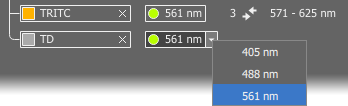
Figure 164.
Select Channel Series
Select the preferred Channel Series mode in the pull-down menu above the spectral graph. The acquisition order of channels will be calculated automatically and indicated in the spectral graph as follows:
 Fastest
 All channels are captured at once. 1: DAPI + FITC + TRITC
 Balanced
 It is a trade-off between speed and minimized crosstalk. Wavelengths are captured in pairs so that there is a sufficient gap between the wavelengths. In our example, the sequence will be: 1: FITC, 2: DAPI + TRITC
 Minimal crosstalk
 Each channel is acquired separately starting from the highest emission wavelength. 1: TRITC, 2: FITC, 3: DAPI
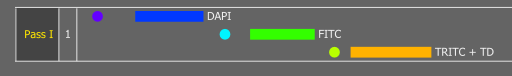
Figure 165. Scan Mode: Fastest
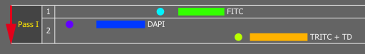
Figure 166. Scan Mode: Balanced
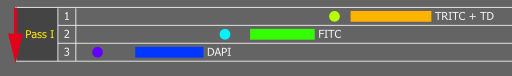
Figure 167. Scan Mode: Minimal Crosstalk
Try Automatic Experiment Settings
(requires: DUX-VB)
The following buttons can be used to calculate optimal assignment of lasers, channels, detectors and software/hardware passes. As opposed to the Channel Series option which determines only the order of lasers in which they are used, these buttons calculate all possible combinations and modify the entire preset to best suit the preference.
Adjust Filter Range
(requires: DUX-VB)
You can move the limits of variable filters by mouse to change the bandwidth.
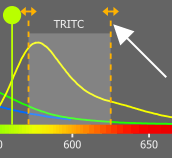
Figure 168.
Save the Preset
When everything is set, click on the or the button.
If you create an experiment setup based on dyes you may select your favorite dyes in the process. From that moment on, those dyes will appear at the top of the list of dyes.
Create an experiment with the Based on Dyes option selected.
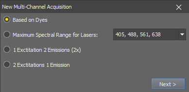
Figure 169.
Note
Experiments which use IR lasers are always based on dyes, so this step is skipped.
A window for adding dyes to the experiment setup appears. Click on the
 button next to the search field to display the list of dyes.
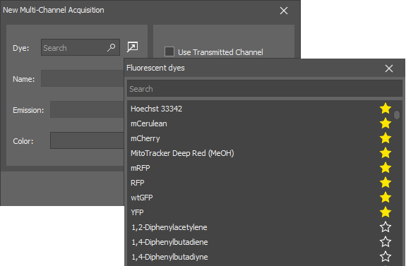
Figure 170.
Dyes marked by the
 icon precede the others.
You can freely select or deselect the favorite dyes by clicking on the
/ icons. Next time you open the list, it will be re-ordered by the preference.
Enter the edit mode by the button. The following buttons can be used to calculate optimal assignment of lasers, channels, detectors and software/hardware passes.
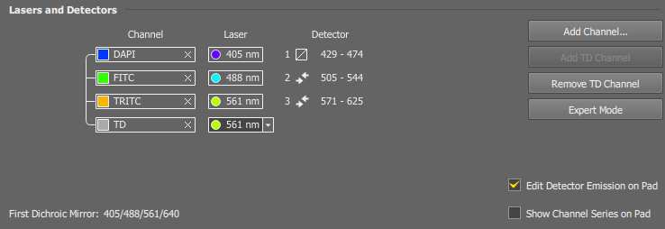
Figure 171. Default edit mode on a DUX-VB4 system
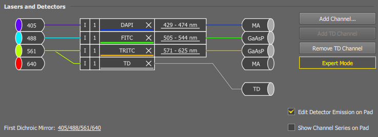
Figure 172. Expert edit mode on a DUX-VB4 system
This section displays assignment of lasers, channels, filters and detectors and enables the user to edit them. Depending on the selected type of experiment, the following options are displayed, or appear after you click the button.
Adds another channel to the list of channels for acquisition.
Adds a channel which will contain signal from the transmitted detector.
Removes the TD channel.
Extends editing options of the current setup.
Select position of the first dichroic mirror.
Select a pre-calculated order in which the channels are scanned. The preference is always to start from the longest wavelength and end with the shortest.
Fastest Maximum of channels are captured together. If there are more channels than the number of installed lasers, the acquisition sequence will be divided in multiple passes. There can be up to 4 passes.
Balanced A trade-off between speed and minimized crosstalk. Usually, channels are acquired in pairs.
Minimal Crosstalk Channels assigned to different lasers are acquired separately starting from the highest emission wavelength.
 Custom
 In this mode, channels can be arbitrarily ordered and divided into multiple “software” passes. For example like this:
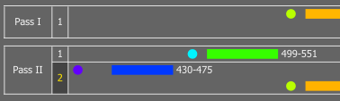
Figure 173. Custom Scan Mode
If this option is selected, buttons for quick changing of the channel series (scan) mode will be present in the AX Pad panel.
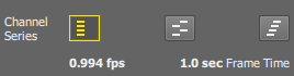
Figure 174. Channel Series on AX Pad
Enables separate averaging settings for each channel. However, averaging of the channels captured at once (within the same channel series step) is synchronized. For absolute freedom in the averaging settings, select the Minimal Crosstalk channel series mode. A slider for each laser line appears in the AX Pad panel.
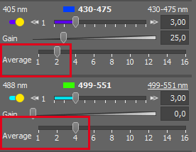
Figure 175. Individual averaging
If selected, limits of the variable filter can be edited straight on the AX Pad panel
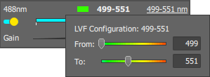
Figure 176. Editable emission range on the pad
(requires: MP)
If selected, wavelength of the tunable IR laser can be changed from the AX Pad panel.
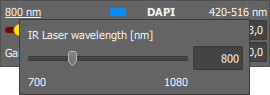
Figure 177. Editable laser wavelength on the pad
Note
Do not forget to re-align the laser every time you change the wavelength.
Saves changes to the currently selected preset. If you edited a default preset, this button is disabled.
Saves the current settings as a new preset. The user can define its name.
Leaves the edit mode without saving any change.
Spectral Mode
(requires: DUX-VB)
Select lasers to be used for excitation during spectral acquisition.
Note
If one or more lasers are not compatible with the selection of the First Dichroic Mirror the corresponding laser is displayed as a dashed line in the spectral graph.
Specifies the way the lasers are turned ON and OFF. Channels are acquired from the longest emission wavelength to the shortest.
 Sequence
 Only the laser with the nearest lower excitation wavelength than the emission wavelength is turned ON.
 Cascade
 All lasers are turned ON at the beginning, once the filter range gets close to the excitation wavelength, the highest excitation wavelength is turned off.
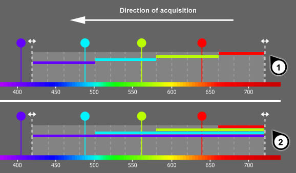
Figure 178. Excitation modes
(requires: DUX-VB4)
Since there are two detectors equipped with a linear variable filter in the VB4 configuration of the microscope, you can select which one will be used.
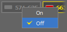
Select whether to include the transmitted light detector and capture the TD channel. Select the excitation wavelength for the channel from the pull-down menu.
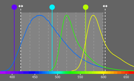
Laser wavelengths, filter ranges and dye emission and excitation spectra are indicated here.
Displays not only emission, but also excitation spectra of the used fluorophores in the spectral graph.
Displays all spectra of the current experiment in the graph. Otherwise, only spectra of the pass selected by mouse are displayed.
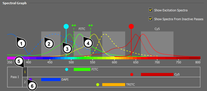
Figure 180. Spectral graph of an advanced multi-channel experiment
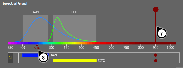
Figure 181. Spectral graph of a multiphoton experiment (requires: MP)
DAPI excitation - displayed because both checkboxes are selected.
DAPI emission - displayed because both checkboxes are selected.
FITC excitation - displayed because Show Excitation Spectra is selected.
FITC emission - displayed because emission of an active pass is always visible
Active pass #1, lasers of the pass #2 are hidden from the graph.
Inactive pass #2.
Indicated wavelength of the IR pulse laser. (requires: MP)
Half of the IR laser wavelength where “Second Harmony Generation” (SHG) can occur. (requires: MP)
Note
The selection of passes is for visualization purposes. It has no effect on the scanning procedure.
If a fluorescence lightpath is selected in the Acquisition  panel, an area where you can create experiment presets and quickly switch between them appears. There are the following tools.
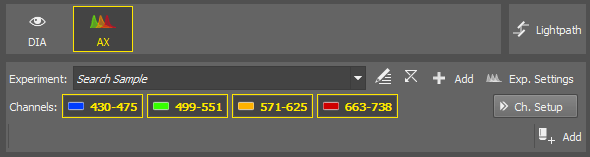
Figure 182.
The pull-down menu contains all presets valid for the current light path.
 Defaults
 Resets power, gain, pinhole size and averaging to default values. Defaults can be adjusted in the  Configure window.
See Defaults.
Exp. Settings Experiment settings. Allows the user to create and edit experiment setups (device presets).
See Experiment Settings.
 Ch. Setup
 If you need to simulate the order of channels which will be used during acquisition, turn on this button. Channel buttons will then behave according to the experiment setup. For example, if 4 channels are acquired and the Balanced channel series mode is selected, then two pairs of channels are acquired at the same time. If you select the first channel button for live display, the whole group of two will be turned on.
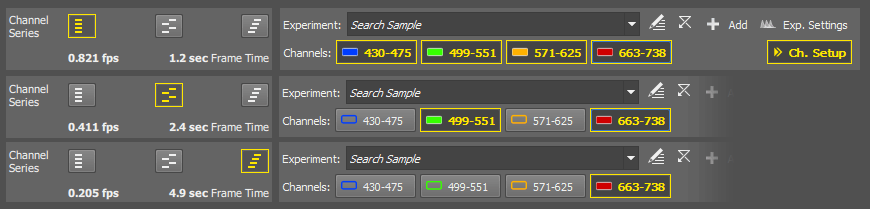
Figure 183. Different active channels in different channel series modes