
Image

Image (captured)
Binary Image (overlay)
Volume View
Split components
Annotations and measurements
Intensity profile
ND Information
Scale
ROI
Update - updates the settings for the corresponding objective in a matching existing experiment. The experiment is then selected automatically to achieve the same acquisition conditions as in the source document (provided the document was acquired on this system). Settings for other objectives and modalities remain unchanged.
Rename - renames the matching existing experiment and creates a new one. The new experiment applies the settings from the source document for the corresponding objective, while other objectives and modalities are set to their default settings. The new experiment is selected automatically.
Overwrite - works the same as Rename but deletes the original experiment instead of renaming it.
 Add Attachment
 Append an arbitrary file to the currently opened image document. The Select Attachment window appears, where you can specify the appended file.
Add this Point to ND Acquisition Appends a line to the current multipoint experiment table including the PFS offset.
Clear All Objects and ROIs Erases all vector overlay layers of the current image i.e. annotations, measurement objects, ROIs.
Colorize Binary by 3D objects, Colorize by 3D objects Having a Z-stack image and a 3D binary. This command colorizes the 3D objects to easily determine if two neighboring objects are connected or not. This command is available on a context menu over Volume View and Slices View.
The 3D binary is created by one of these commands:
Colorize Binary Objects This function displays the binary objects in several different colors. The algorithm is optimized so that two neighboring objects would never display in similar colors.
Connect 3D Objects in Binaries (requires: Standard)
Connects Z-stack slices of 2D binary objects into 3D binary objects. It equals the  Binary > Connect 3D Objects in Binaries command and appears in the context menu when the image is displayed in Volume View.
Copy Binary This function copies current binary image (in case of ND) from selected (visible) layers into clipboard. The copied binary layers can be inserted into another image or as a new image.
Copy Binary Layers The function copies binary layers into the clipboard. The layers can be pasted into different documents.
Correlation Properties... Displays the Correlation Properties dialog window used for defining the correlation view.
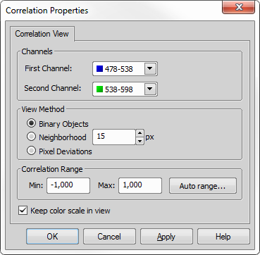
Figure 2077.
Changes the correlation range (minimum and maximum values). Click to determine a proper range automatically.
Select a correlation method:
Binary Objects - computes the Pearson's correlation coefficient for each binary object.
Neighborhood - Pearson's correlation coefficient is computed for a square neighborhood of each pixel. Define the neighborhood size in pixels using the spin box.
Pixel Deviations - is calculated as a covariance per pixel.
Correlation View Turns the Pearson's correlation on and off. It is used to visually interpret the relation between two image channels and to see which areas in the image are correlated.
Start by thresholding your image (see: Thresholding) to determine the areas where the correlation will be calculated. Then define the channels and method in the Correlation Properties dialog (Correlation Properties...) and confirm the settings by clicking . Now run this function to calculate the correlation.
Hovering over a thresholded area shows the Pearson's correlation value on the bottom right side of the image window. It takes values from -1 to +1 (default Correlation Range), where -1 is a total negative linear correlation, 0 is a no linear correlation and 1 is a total positive linear correlation.
Find this Point in Paired Document If two images have matching XY coordinates, this function can be used to locate the position in one image inside the other one.
Object Visibility Sets visibility of the currently selected annotation/measurement object(s) over time.
 Clear Selection
 Finish
 Help
Help Invert Selection
 Select All Frames Open File Location
 Opens the current image in Organizer ( View > Visualization Controls > Organizer  ).
).
Paste Binary Layers The function pastes binary layers from clipboard into current document. Clipboard must contain some binary layer.
Paste Objects This function inserts all vector objects that are currently in the application clipboard to the current image. Some vector objects must have been copied to the clipboard previously.
Reuse > Reuse Camera Settings Sets the camera settings to match the settings of the specified image file. The *.TIF, *.ND2 and *.JP2 file formats are supported. This function is invoked on the context menu in Opened Images and Auto Capture Folder control windows.
Reuse > Reuse Device Settings Loads device-related metadata from an image file and sets the connected device(s) accordingly. The *.TIF, *.ND2 and *.JP2 file formats are supported.
Reuse > Reuse Experiment Selects an experiment from the document and sets the corresponding objective position. If an experiment with the same name already exists, the user is asked to select one of the following options:
Reuse > Reuse ND Setup Sets the ND setup to match the settings of the specified ND image file. The *.TIF and *.ND2 file formats are supported. This function is invoked on context menu in Auto Capture Folder and Opened Images control windows and also on the button in Image Properties dialog box.
ROI Properties This command opens the ROI Properties dialog window where visual parameters of the ROIs can be set.
Set Document as Uncalibrated... Removes the current image calibration. The image becomes Uncalibrated.
Show LUTs Intensity Range Shows or hides the LUT visualization bar. LUT visualization bar is overlaid on top of the image.
Show ND Information This function displays summarized ND information (information about the current frame of an ND2 document or live image).
Show Physical Zoom Displays value of physical zoom (real magnification of the sample) in a box in the top left corner of the image. To hide the box, right-click on it and select Hide Physical Zoom.
Note
Correct monitor calibration is required by this function to work correctly. See Monitor Calibration.
Show Thumbnail of Merged All Channels Sets the option whether the sub-view with all channels should be present in the Split Components viewing mode.
Show Thumbnail of Merged Custom Channels Sets the option whether the Custom sub-view should be present in the Split Components viewing mode.
Toolbars This function quickly changes the appearance and behavior of image toolbars. The same options are accessible in program options.
See Appearance Options.
Use all XY locations as preview in XYZ Overview All multipoints present in the image are shown in the preview of the XYZ Overview panel.