
Click the  Configure button on the
  AX Pad panel to display the settings window. There are several tabs:
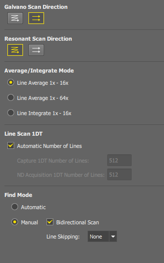
Figure 222.
Sets the preferred scan direction.  Unidirectional scan or
  bidirectional scan is available for each scanner. The bidirectional mode is faster but needs to be aligned properly in the
  Alignment tab. If this mode is misaligned, a message and info button will appear, allowing you to click the
  button and align it Automatically or Manually.
Caution
In Galvano mode, bidirectional scanning is reserved for resolutions 1024 x 1024 and smaller. You can select the bidirectional mode here, but when higher resolutions will be set, the scanner will switch to a unidirectional mode automatically.
Select the noise-reduction method and the range of frames which will be available in the AX Pad panel.
The automatic number of lines is 512 for all line lengths. De-select this option to set the size manually.
This value is used with the  Acquire > Capture command.
This value is used in ND Acquisition experiments.
This mode is designed to provide a dedicated find function for searching, focusing, and adjustment. It uses a real image with an unskipped center area (approximately 25%) while applying rolling skips to the surrounding borders.
Table 3. Find mode scanning parameters for galvano full FOV scan.
| Number of line series | FPS | X resolution | Line skip | Non-skipped band |
|---|---|---|---|---|
| 1 | 4.5 | 512 | 4 | 25% |
| 2 | 4.3 | 256 | 4 | 25% |
| 3 | 2.8 | 256 | 4 | 25% |
| 4 | 2.1 | 256 | 4 | 25% |
Optionally, you can set the find-mode parameters manually. In this mode, no image enhancement is applied.
Use bi-directional scanning mode.
Frame rate can be increased by skipping lines. Line skipping 2x scans every second line, line skipping 4x scans every fourth line.
If this option is displayed, your laser unit is equipped with a controllable mechanical shutter.
A mirror is used to redirect the lasers out of the optical path when the device is idle. Minor intensities could reach the sample in this mode even though.
Choose this option to prevent any light to reach the sample during idle phases of work.
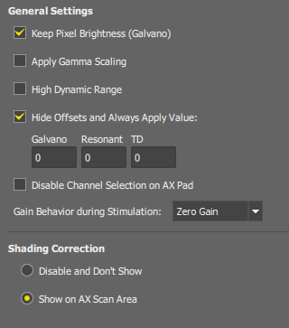
Figure 223.
This option allows you to acquire images with their brightness unchanged even if the Pixel Dwell Time is changed. It works only with the galvano scanner type.
This function uses a gamma curve to lighten dark areas of the image. This option is only applied if the High Dynamic Range option is selected.
The original (wider) dynamic range of the detectors is re-calculated to the 12-bit range of the resulting images. With this option ON, the whole range of the detector is used, otherwise, the range is slightly cropped.
Hides sliders in the AX Pad panel and applies the offset values specified here. Different offsets can be specified for galvano/resonant modes and the TD channel.
If selected, channels can be turned ON/OFF arbitrarily in the Experiment panel.
Detector gains can be controlled automatically during stimulation experiments in order to handle the case when a PMT overload occurs.
Sets the gain on all detectors to 0 during stimulation. The original gain is restored after stimulation. PMT overload cannot occur.
The automatic gain control is turned OFF - the gain remains unchanged. If PMT overload occurs, a red alert appears in the AX Pad panel. The user must adjust the gain manually to restart the detector.
The gain remains unchanged. A PMT overload can occur, but the detector is recovered automatically after the stimulation.
Hides the button on the AX Scan Area panel. Does not apply any correction.
Displays the button on the AX Scan Area panel.
Select the format how the FPS and Frame Time values are displayed on the AX Pad panel.
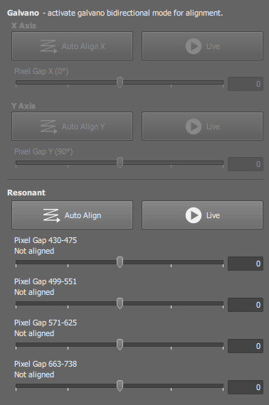
Figure 224.
When bidirectional scan mode is selected in the Acquisition tab, a shift between even and odd lines may occur in the image. You can correct the shift here.
Only the active scanner can be aligned, if the buttons are disabled, close the window and activate the other scanner in the AX Pad panel.
 Activate Manual Alignment
 Starts scanning and displays the live image window. You can check influence of the alignment.
Auto Align, Auto Align X, Auto Align Y Runs a dedicated algorithm which calculates the pixel gap automatically based on a series of captured images. Make sure the sample for automatic alignment has distinct texture and minimum noise.
Note
The galvano scanner enables rotation of the scan area. Therefore alignment of the Y direction is performed with the scan area rotated by 90 degrees.
You can adjust the pixel gap manually. Either drag the slider by mouse or type a value to the edit field on the right.
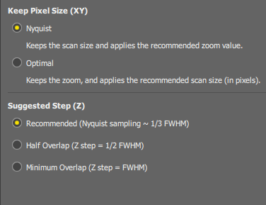
Figure 225.
Determines behavior of the / button which adjusts scan area parameters automatically in order to achieve optimal pixel size. When the button on the AX Scan Area panel is pressed:
The scan size remains unchanged and the zoom size value is adjusted automatically.
The zoom size remains unchanged and the scan size (image resolution) is adjusted automatically. The resolution which provides the closest value of the pixel size to the Nyquist resolution will be selected.
Select how the suggested Z-step value is computed in the ND Acquisition Z series settings window.
It is computed as a ratio of the optical section thickness (optical section thickness = FWHM of the Z airy disc).
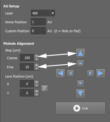
Figure 226.
This is the default state.
The user sets the AU value.
The software computes the physical size (µm) based on the current objective and the requested wavelength.
If symbolic wavelengths are used (Shortest, Medium, Longest), the physical size is recalculated for each software pass, according to the actual wavelength of that pass.
This means that in quality sequential experiments, the pinhole size may change between channels (the pinhole moves inside capture).
The user sets the physical size (µm), derived from the AU computed under the current settings.
When symbolic wavelengths are used (Shortest, Medium, Longest), the software considers all wavelengths in the experiment.
In this mode, the AU value remains fixed when the active software pass changes, so the physical pinhole size is stable across channels.
This setting controls how the pinhole size is adjusted when changing wavelength, objective, or scan parameters.
Keep AU (checked)
Keep AU (unchecked)
Select a wavelength from which the AU is calculated.
One of the lasers used in the experiment will be used.
Sets a default position for the pinhole. This pinhole position is set by the button in the AX Pad panel.
Sets a user-defined pinhole position and displays an additional shortcut-button in the AX Pad panel. If the value is 0, no button will be displayed.
The pinhole position can be aligned by manually shifting the condensing lens.
Use these edit fields to define step for the arrow buttons.
Change the X and Y lens position by either clicking on the arrow buttons, typing inside the X and Y edit fields or clicking on the spin buttons.
Live Display the live image by this button to see how the alignment affects the image.
Note
Different alignment settings are remembered for each position of the 1st dichroic mirror and different alignment is also used if the second laser port of the AX head is used (FLIM/FCS applications).
Note
Pinhole size in AU is shown in the Acquisition details pane (see: File > Image Properties).
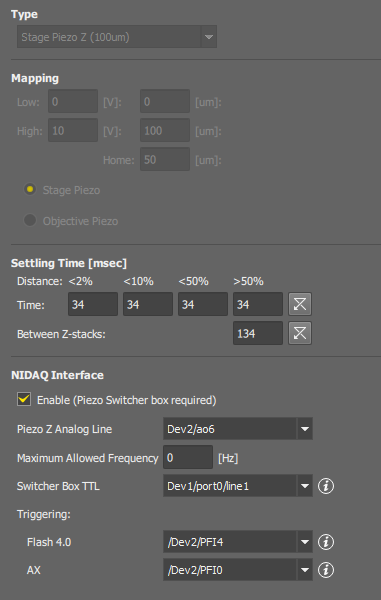
Figure 227.
MCL 100 µm stage piezo
MCL 200 µm objective piezo
MCL 450 µm objective piezo
PI 400 µm objective piezo
THK 400 µm objective piezo
Any other piezo controled by voltage
Displays the current type of the Piezo Z stage. The following devices are supported:
If a custom piezo Z stage which is not directly supported in the software is used, this section gets enabled. Mapping between voltage and position of the stage can be adjusted here.
Forces the specified delays so that the Piezo drive has time to settle.
The piezo switcher box allows you to trigger a piezo Z stage by the AX controller or a camera without re-connecting of cables.
Select this option if the box is included in your hardware setup.
Select a NIDAQ port connected to the NIDAQ connector on the switcher box.
Maximum number of direction changes performed in a second. Use this option to prevent wear of the hardware.
Select a NIDAQ port connected to the SET connector on the switcher box.
Select NIDAQ ports connected to the trigger OUT signals of the cameras used.
(requires: Local Option)
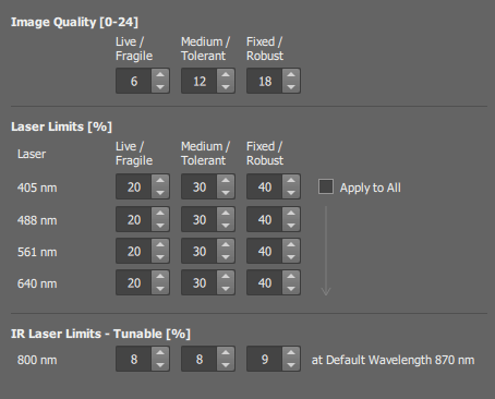
Figure 228.
Each column represents values used with different Autosignal.ai setting.
Select the preferred image quality for each setting.
Note
The higher the number is, the higher is the risk of bleaching the sample. Make sure the values are low-enough not to ruin your sample but high-enough to get as good an image as possible.
Maximum laser power which can be set by the AutoSignal.ai button.
Select this option to use just one setting for all lasers.
(requires: MP)
Maximum laser power which can be set by the AutoSignal.ai button.
(requires: MP)
Maximum power or the IR laser which can be set by the AutoSignal.ai button for the default wavelength. For other wavelengths, the power is recalculated according to the laser calibration curve. See Defaults-MP.
The default option, Find Acquisition (faster), enables AX auto focus to use the Find mode for acquisition. In this mode, AX checks the FPS, and if it is below 7, it reconfigures the system for faster performance. To revert to the original behavior, select Regular Acquisition, which applies the same settings used for the standard Live/Capture modes.
(requires: MP)
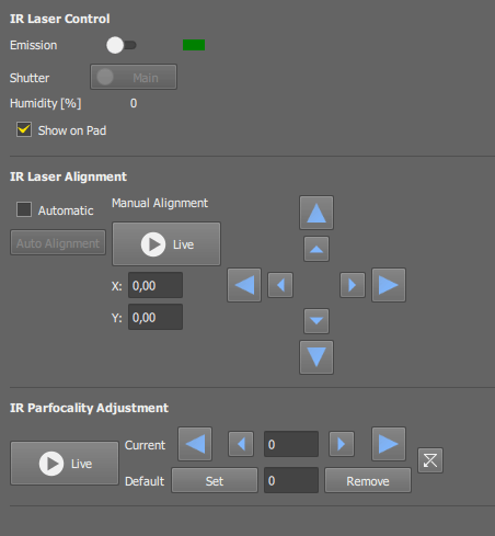
Figure 229.
If you close the dialog, the value remains set
If you change the objective or laser wavelength, this value will be reset to default (see below).
Select this option to display the IR laser control on the AX Pad panel.
Option of the Insight X3 IR laser. If periodic noise has been observed during sensitive measurements, the servo may be turned off for future measurements. It is recommended to turn the servo back on as soon as a measurement is completed.
Note
The servo will be automatically turned on after 60 [min] in order to maintain laser performance.
Optical XY alignment of the IR laser is different for each laser wavelength. There is an automatic alignment mechanism which should be run every time the wavelength is changed.
If selected, automatic XY shift alignment will be performed after the IR laser wavelength is adjusted.
Click this button to run automatic alignment at once.
Or, the shift can be adjusted manually by the arrow buttons.
Parfocality of the IR laser can be adjusted by the user.
Run the live image. Click on the arrows to adjust parfocality offset for the current objective.
Note
If the configuration contains two IR lasers (Dual IR) both with adjustable parfocality, a separate adjustment section appears for each (Main and Sub).
(requires: Local Option)
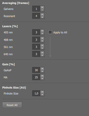
Figure 230.
Default settings for lasers, gains, averaging and pinhole size. These values will be set after you press the  Defaults button on the AX Pad panel.
Select this option to use just one setting for all lasers,
Sets default values to all fields in the tab.
(requires: MP)
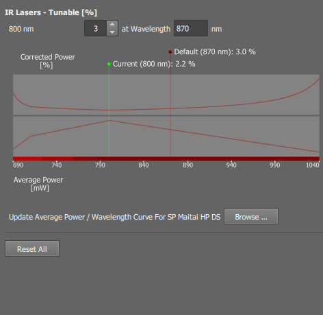
Figure 231.
Default settings for IR lasers. These values will be set after you press the Defaults button on the AX Pad panel.
Set the default laser power in percents for the fixed-wavelength laser.
Set the default laser power in percents for the tunable-wavelength laser.
Fill in the wavelength at which you achieved the optimal laser power you want to set as default.
Note
Each tunable laser has a wavelength-power calibration curve. The actual (physical) laser power used at different wavelengths is corrected according to this curve.
If this message appears, there is no calibration curve available. Use the button to load a TXT file containing the calibration curve.
Sets default values to all fields in the tab.
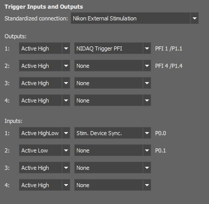
Figure 232. Default IO settings
Sets triggering input and output signals of the AX control unit. There are 4 inputs and 4 outputs on the AX controller.
(requires: NSPARC)
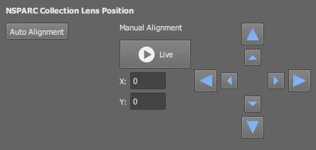
Figure 233.
Click this button to determine optimal position of the collection lens automatically. It should be sufficient in most cases.
Change the X and Y position of the collection lens by either clicking on the arrow buttons or typing inside the X and Y edit fields.
Live Display the live image by this button to see how the alignment affects the image.
If needed, you can adjust the Level parameter (deconvolution strength) for the Live Deconvolution for SR Mode option on the AX Pad panel.
Enables to save NSPARC raw image data along the captured image.
See NSPARC Control.
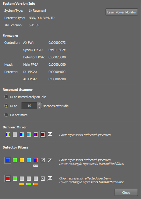
Figure 234.
Select laser wavelength.
Click the button. A new row will be added to the table.
The result is a unitless value displayed in the last column. Perform this measurement whenever you suspect there is something wrong with the lasers. If the value differs a lot from the previous measurement it is a sign you should contact your local dealer of the system to request support.
In the
Devices > Device Manager  window, click
  right mouse button on the Confocal Ax device and select the Optimizer command.
After confirmation, it will take approximately 35 seconds for each laser line to perform the “Cool AC” (constant optical output level - auto calibration) procedure,
Various system information
Click this button to verify actual power of the installed lasers. A laser-power monitor window appears.
Optimizer
This function is related to lasers manufactured by . You can run an auto-calibration procedure to maintain their output level constant.
(requires: AX-SHR)
The resonant scanner produces noise which you may want to suppress. When the Resonant sound reduction function is used, the scanner resonates only during scanning (Live, capture image, ND Acquisition). Select when or whether to turn the resonant scanner OFF.
The disadvantage of these options is that a ~1 second delay needed to stabilize the scanner resonance will occur when starting live image or acquisition.
The noise is not suppressed.
Muting only reduces frequency of the scanner. This option turns off the scanner completely. However, the delay before the live image will be longer by seconds.
These sections display the current filter setup of the 1st dichroic mirror and the detector filter wheels. You can re-assign the filters if you change them inside the device. The fill colors represent reflected wavelengths and the smaller rectangles below them represent transmitted wavelengths.