Select a calibrating Method from the combo box (defines how many points have to be added for each well).
Choose a well in the wellplate preview and click on in (Recommended Wells are colored in gray).
Display live image from the camera. A cross will be displayed in the image.
Move the XY stage so that the edge/center/corner (based on the chosen method) of the well is in the center of the cross.
Click .
Now use the stage to add more edge points on the same well (add as many points as you selected in the Method combo box; e.g. for Center Point one is sufficient). If all calibration points of a single well were correctly added, the well is highlighted green.
Choose a second well in the wellplate preview and click on it.
Add calibration points for this well (repeat procedure from step 3).
If done properly, two wells are calibrated (highlighted green) and the well plate is correctly aligned. To increase accuracy of the alignment, calibrate more than two wells.
Click the button and follow the instructions to initialize your plate loader.
Scan for the loader hotels by clicking the button.
Select / deselect the plates and hotels found to be used in your job.
Add notes to each of your plate if necessary.
 Define Plate
 This task specifies shape and size of a well plate as well as the working area of single wells. Select a wellplate type you use from the database or define a custom wellplate. The wellplate definition includes dimensions, number of wells and placement of wells. | Requires: Device: Motorized Stage |
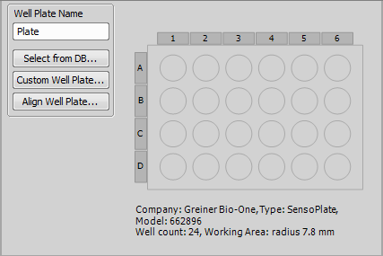
Figure 1194.
This button opens the well plate database, where you can find many standardised well plates.
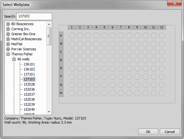
Figure 1195.
This function opens the Define custom well plate window where it is possible to adjust all key parameters of nonstandard well plates. Please see Custom Well Plate Options.
Opens the Re-Align Well Plate dialog window. Please see Well Plates >  Align Well Plate Holder.
Note
Well plate alignment can be done inside the job definition using the Well Plates > Align Well Plate Holder and is job dependent - has to be repeated with each new job. It is also possible to align the plate globally by HCA/JOBS > Well Plate > Align Well Plate Holder. This alignment is saved into the database and applied on new well plates automatically.
Custom Well Plate Options
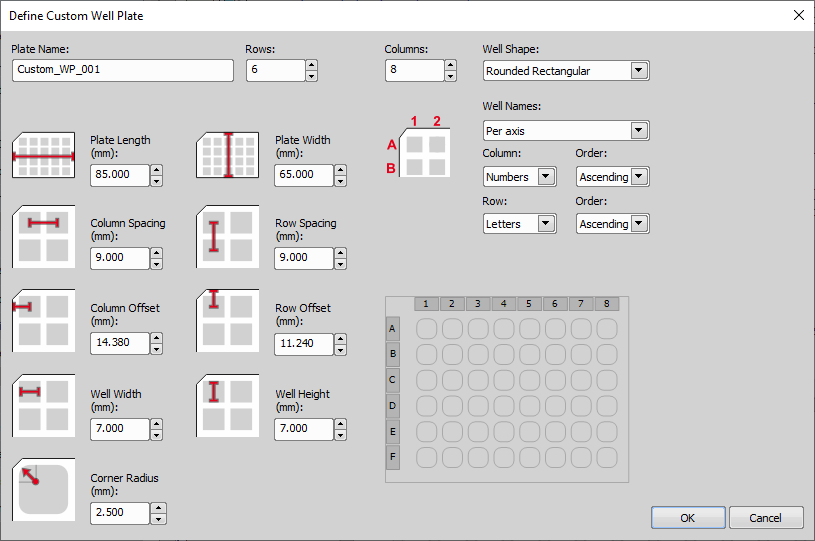
Figure 1196.
Type the name of your well plate.
Type how many rows does your well plate have.
Type how many columns does your well plate have.
Select which shape does your well plate have. Circular, Rectangular and Rounded Rectangular are available.
Here you can choose the single well labeling method. The Per axis method labels the wells with letters and numbers, applicable on both axis. The Per well method labels the wells from number one, from the left side to the right side and from top to bottom. Specify your choice in the Column and Row combo box.
Define size of the wellplate.
Define distances between adjacent well rows.
Define distances from the edge of your plate to the center of the A1 well.
Define the diameter of a single circular well.
In case of rectangular well shape, define its height and width.
If you are using a Rounded Rectangular well shape, here you can set the corner radius in [mm].
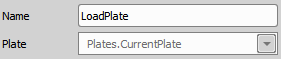
 Use Autodetected Plate
 This task selects the globally stored auto-aligned well plate as the well plate to be used inside a particular job. |
Align Well Plate Holder This function determines the exact position of a well plate on the XY stage. Typically, this task is executed during runtime. Before a wellplate is scanned, it must be aligned properly, so that the coordinates of wells are not misplaced. Select wellplate orientation and find the A1 well. | Requires: Device: Motorized Stage |
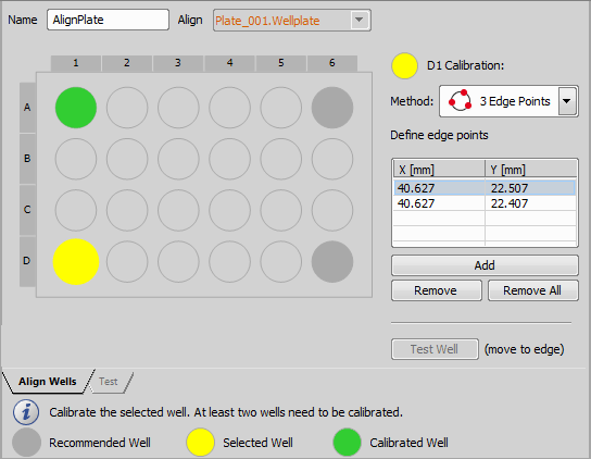
Figure 1197.
Correct Wellplate Alignment - Well Calibration
For a precise alignment, at least two wells should be calibrated. Each well is calibrated using one or more points based on its shape and selected calibration method. To align your wellplate correctly follow this procedure:
Note
The more wells you calibrate, the more well plate alignment imperfections are eliminated. Two calibrated wells can rectify the XY position and rotation of the well plate. Three calibrated wells can rectify the XY position and a slight tilt of the well plate. Four calibrated wells can rectify the XY position and a large tilt.
However one well is also enough for rough calibration. If one well is used for calibration it is assumed that the whole well plate is placed orthogonally on the stage with its top-left well oriented to the top-left stage corner.
Align Wells tab
Choose a well plate defined by the Well Plates > Define Plate which will be aligned.
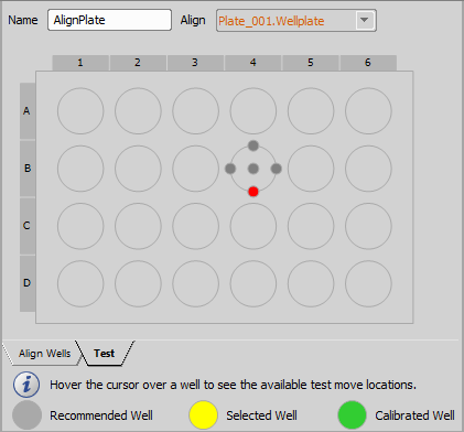
Figure 1198.
Test tab
This tab is useful for checking the correct alignment of the whole well plate. Hover the cursor over any well. Available test move locations are displayed. Click on a gray circle to move the stage to this exact position and verify the alignment precision.
 Detect Plate Automatically
 Automatically detects and aligns the well plate on the stage. AI driven algorithm is used for the detections. The result is stored globally - one auto-aligned well plate can be used by any other job or by Well Plate and Slide Navigation. Advantage of this task is that it is not necessary to align the plate holder on the stage or to know/define an exact plate type. It can be directly used by the Well Plates > | Requires: Device: Motorized Stage, 4x objective |
The AI network was trained with the Sample Swap position set in the Autofocus + Focus Surface >  Move to Predefined Z Position task. Always choose the Sample Swap position before plate auto detection to ensure proper Z positioning, as shown in the example below.
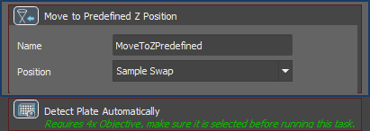
Figure 1199.
 Select Wells
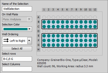
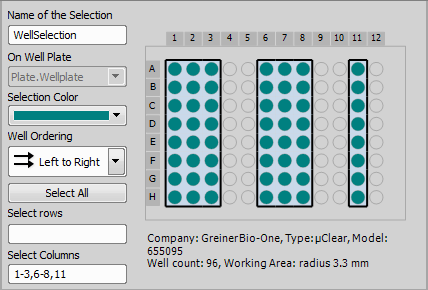
 Specifies which wells of the selected well plate are actually used in the experiment. Use the A1 well for alignment and leave the outer perimeter of wells unused. | Requires: Device: Motorized Stage |
Before selecting any wells you need to define the well plate by the Well Plates > Define Plate task. After the plate definition, you can select the wells using the Select Wells task. The wells can be easily selected by clicking and dragging over the well board. If you hold down the shift key, you can select remote parts of the well plate. If you hold down the control key and drag over wells already selected, you exclude them from your actual selection. You can also select single rows / columns by clicking on their letter / number. If using mouse for the well selection, the selected values automatically appear in the Select rows or Select columns fields where you can manually rewrite them using comma (for separating the values) and dash (for entering range values).
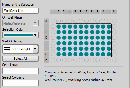
Figure 1200.
 Empty/Full Well Selection
 Creates a well selection with either all wells selected or de-selected. Use it before a loop over wells to reset the selection before it is modified within the loop. | Requires: |
 Add Well to Selection
 Adds a well to an existing selection of wells. Use it inside Well Plates > | Requires: |
 Condition (If)
 Remove Well from Selection
 Removes a well from an existing selection of wells. Use it inside Well Plates > | Requires: |
 Edit Well Selection
 This task enables the user to manually adjust the automatically generated well selection at run time. The user can modify the selection of wells right after detecting the cells using AI. | Requires: |
 Use Well Selection from Sample Navigation
 This task loads the selection of wells currently defined in the View > Acquisition Controls > Sample Navigation | Requires: |

 Create Well Selection from Point Set
 This task uses a point set to create a new well selection. | Requires: |
 Loop over Wells
 Runs the contained tasks on each well of the selected well selection. Used for wellplate analysis. The wells are either analysed one-by-one (fast timelapse experiments) or in multiple well-loops (e.g. 1: pre-focus all wells, 2: capture each well). | Requires: Device: Motorized Stage |
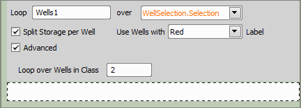
Figure 1203.
This option influences how the system stores the captured data on the disk. If checked, separate ND2 file will be created for each well.
If your wells are labeled (by the Well Plates >  Label Well Plate task), you can loop only over wells marked with the selected label.
If you select this option, the Loop over wells will be performed only on wells with defined class typed in the Loop over wells in class field. The class number can be assigned to each well using an expression. The Class can be defined in the System >  Expression task - find a parameter named “Class” under Job / Name of your Well Loop / CurrentWell / Class. Insert this expression by double-clicking on it and use given operators to define your class (e.g.: Job.WellLoop.CurrentWell.Class=2). In our case “2” is the Class we fill into the Loop over wells in class field.
Under the current well of the WellLoop there is also a Skip parameter under CurrentWell which is 0 (FALSE) by default. It can be changed in the System > Expression or System >  Macro task inside this WellLoop or outside (different WellLoop). When set to 1 (TRUE), the well will be skipped next time when visited by any WellLoop (e.g. in a Time-lapse). The Skip parameter (same as Class and Labels) is on every well. The WellLoop makes it only available for current well under CurrentWell parameter. Therefore, when it is changed for a given well all other Well loops can see it.
if (totalCells > 10000)
   Job.Wells1.CurrentWell.Skip = 1;
where the Wells1 is the name of the task.
The node itself exposes a read-only parameter ValidCount reflecting the number of wells visited while taking into account skipped wells due to the Skip, Class and Labels parameter. It is useful for terminating a loop that runs over a WellLoop (typically a time-lapse) that is already skipping all the wells.
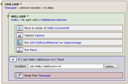
Figure 1204.
Complete example using the Skip and ValidCount based on GA3 result can be found here.
Note
Loop over Wells does not move between the wells on a well plate by itself. It is therefore impossible to expect pictures of single wells by placing just Capture inside the Loop over Wells. To do so, you have to place the Move to Well Center task (Well Plates >  Move to Well Center) inside the loop right before capture. This task tells the loop to move to the appropriate well.
Label Well Plate Enables the user to label, dosing or custom labels to each well or a group of wells. Label positive, negative and control wells and add the quantity of the solution used so that the analysis results can be sorted based on the given label. | Requires: Device: Motorized Stage |
Unfold your Well Plates > Label Well Plate task inserted into the Job definition window by double clicking on its caption and then click  to open the Labeling and Dosing window (closely described here: Labels). To clear all the defined labels click
  Clear All.
 Use Well Labeling from Sample Navigation
 This task loads the labeling of wells currently defined in the View > Acquisition Controls > Sample Navigation Set the labeling outside of JOBs in the main application (e.g. in Sample Navigation) and then use it in JOBs. |
 Export Well Labeling to Sample Navigation
 This task exports the well labeling done in JOBs into the View > Acquisition Controls > Sample Navigation Set the labeling in JOBs and the re-use it in the Sample Navigation panel. |
 Export Well Selection to Sample Navigation
 This task exports the well selection done in JOBs into the View > Acquisition Controls > Sample Navigation Set the well selection in JOBs and the re-use it in the Sample Navigation panel. |
 Plate Loader
 This task communicates with the well plate loader connected to your system. Put this task to wizard to initialize the loader and scan hotels for wellplates just before the experiment begins. | Requires: Device: Well Plate Loader |
Other dialog options are similar to Well Plates >  Manual Plate List.
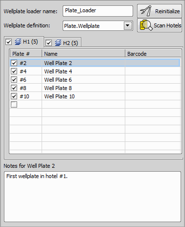
Figure 1205.
Manual Plate List Specifies the list of well plates to be used in a loop over well plates. These well plates are changed manually. Assign names and barcodes to wellplates in an ordered list. This info will be included in the experiment results. | Requires: Device: Motorized Stage |
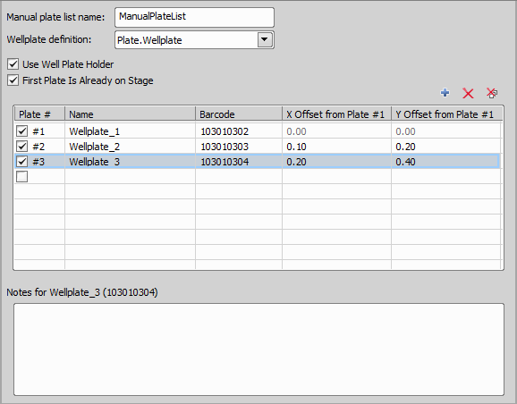
Figure 1206.
 Add New Plate
 Remove
 Remove All
 Loop over Plates
 Runs the contained tasks on each well plate of the specified list of plates. Well-by-well (live) experiments: the whole analysis is inside a plate loop. Fixed/scanning experiments: several plate loops are used in a sequence - 1. pre-focus, 2. capture, etc. | Requires: Module: |
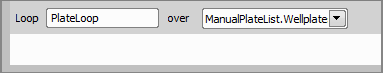
Figure 1207.
Name your plate loop.
Choose a plate list from your current job.
 Move to Well
 Moves the XY stage to a particular well of the specified well plate. Move to a specified well during runtime to check the sample. | Requires: Device: Motorized Stage |
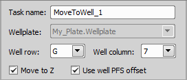
Figure 1208.
If checked, the Z-drive moves to the Z position assigned to the current well (e.g. Z value found by Autofocus + Focus Surface >  Autofocus during the first Well Plates > Loop over Wells).
These options tell the system to set the Z drive to a position previously assigned to the current well.
Note
Particular Z drive position can be assigned to each well by the Autofocus + Focus Surface >  Assign Current Z to Point/Well/Point Set or PFS >
  Assign PFS to Point/Well tasks used within Well Plates > Loop over Wells. The check boxes refer to this Z coordinate.
Move to Well Center Moves the XY stage to the center of the current well. Treatment is usually applied to the well center. | Requires: Task: Well Plates > Device: Motorized Stage |
 Define Stage Area
 Define Slide
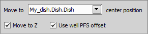
Figure 1209.
If checked, the Z-drive moves to the Z position assigned to the current well (e.g. Z value found by Autofocus + Focus Surface > Autofocus during the first Well Plates > Loop over Wells).
These options tell the system to set the Z drive to a position previously assigned to the current well.
Note
Particular Z drive position can be assigned to each well by the Autofocus + Focus Surface > Assign Current Z to Point/Well/Point Set or PFS > Assign PFS to Point/Well tasks used within Well Plates > Loop over Wells. The check boxes refer to this Z coordinate.
 Move to Previous/Next Well
 Moves the XY stage to the previous/next well. Can be used with a condition during runtime, e.g. when there is a need to get to the previously treated well. | Requires: Device: Motorized Stage |
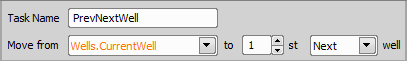
Figure 1210.
 Advanced Loop over Plates
 This task allows full control over the procedure when operating a LiCONiC STX automated incubator. It is important to maintain the objective clearance (escape Autofocus + Focus Surface > This task becomes available when using a Nikon Ti2 microscope in combination with a LiCONiC STX device. Typically the job runs through all plates in the loader and assigns some information to them. For example, all plates are first captured in low resolution, and only those flagged by the analysis (Analysis > | Requires: Module: |
 Escape Z
 Refocus Z
 General Analysis
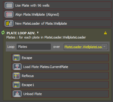
Figure 1211. Manual plate loop procedure respecting the objective clearance, similar to what the Well Plates > Loop over Plates task does automatically.
Name your plate loop.
Defines the plate loader containing plates over which the inner tasks will be executed.
 Copy Well Point Set
 Copies one point set to another point set. In the first step, auto focus is run inside each well on a few points and Z coordinates are saved to the well point set. In the second step, a timelapse over the wells is performed and the Z coordinates from the first step are used to create a focus surface in each well. Thus there is no need to repeat the slow auto focus procedure. | Requires: Device: Motorized Stage |
 Copy Well Selection
 Copies the selected well selection to another well selection. This task works only with identical well plate types. If you capture cells (well selection 1) and there are some cells that show the desired response to a specific concentration of a drug (well selection 2), you can transfer them to different experimental conditions (well selection 3). | Requires: |
Name of your task.
The Well Plates > Select Wells task from which the well selection is copied.
The Well Plates > Select Wells task to which the well selection is copied.
 Continuous Scan of Well Centers
 Requires: Device: Motorized Stage |
A well selection (Well Plates > Select Wells) or plate definition (Well Plates > Define Plate) on which the task will be performed.
If the current speed of the XY stage is reduced for some reason (e.g. by the Stage XY Points >  Set XY Speed/Accuracy task), it will be used.
Use the maximum speed available to achieve the expected result.
 Find Well by Analysis
 A well selection (Well Plates > Select Wells) or plate definition (Well Plates > Define Plate) on which the task will be performed.
A GA3 recipe which is run on each well center an returns numerical results.
 Export Recipe
 Saves the GA3 recipe to a *.ga3 file.
If turned ON, the latest version of the GA3 recipe saved in NIS-Elements analysis database is used whenever the task is executed. If turned OFF, the recipe will be saved as a part of the job and later changes to the original recipe will be ignored.