


 Define Z-Stack
 This task defines parameters required for capturing a Z-Stack (a sequence of images each having a different focal plane). Please see the Z-series Acquisition chapter for details about the Z-stack setup. Create all-in-focus images or 3D models regardless of your sample and depth of field parameters. | Requires: Device: Stage Z |
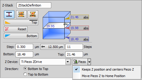
Figure 1251. Defined by top bottom mode
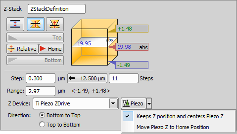
Figure 1252. Symmetric mode defined by range
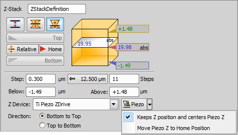
Figure 1253. Asymmetric mode defined by range
Name of your Z-Stack > Define Z-Stack task.
This mode defines the Z-stack using two parallel planes ( ![]() Top and
Top and ![]() Bottom).
Bottom).
Required values: top position, bottom position, step size or number of steps.
This mode defines the Z-stack by its center (Home) position and the same range above and below the Home plane.
Required value: range.
This mode defines the Z-stack by a center (Home) position and a custom range above and below the Home plane.
Required values: above position, below position.
 Reset
ResetChanges the Home (absolute Z) position to Relative (current Z position deducted prior to the actual acquisition).
 Z-Stack Bottom and Top
Defines a Z-Stack simply by its top and bottom positions and step. | Requires: Device: Stage Z |
 Z-Stack Piezo from Bottom
Defines a Z-Stack to be acquired from the bottom position to the top using just the Piezo Z drive. Find the bottom of a cell and capture a Z-Stack with the full range of the Piezo Z drive. See also Z-Stack > | Requires: Device: Stage Z |
 Z-Stack by Expression
 Defines a Z-Stack using absolute coordinates or variables available in NIS-Elements. Use the button to insert variables into the particular edit box. Use this task when you need to define a Z-Stack with absolute Z positions inserted from variables. | Requires: Device: Stage Z |
Global Z Coordinates Use Case
In this following example with an inverted microscope, the stage Piezo Z moves against the direction of the microscope Z-drive and the global coordinates are subtracted. To capture a Z stack for global Z coordinates 10 to 50, the microscope Z-Drive goes to 110 and the Stage Piezo Z goes to 100 (global Z coordinate is 110-100 = 10). Then the Stage Piezo Z moves from 100 to 60 so the final global coordinate is 110-60 = 50.
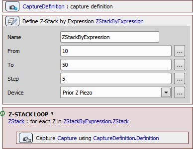
Figure 1254. Jobs definition.
The drawings below show how the global Z value is calculated for different types of Z-devices on different microscopes.
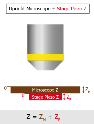
Figure 1255. Upright Microscope with Stage Piezo Z.
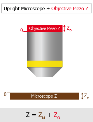
Figure 1256. Upright Microscope with Objective Piezo Z.
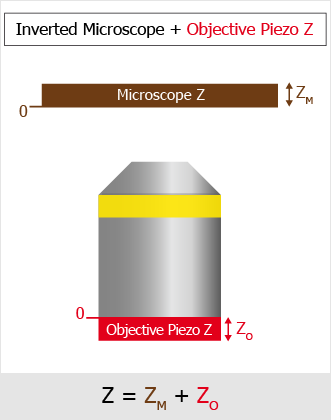
Figure 1257. Inverted Microscope with Objective Piezo Z.
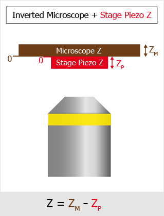
Figure 1258. Inverted Microscope with Stage Piezo Z.
 Z-Stack Loop
 Repeats the contained tasks for each Z position of the selected Z Stack. This task can be used inside any other loop (time-lapse, point set) with Acquisition > | Requires: Device: Stage Z |
 Capture
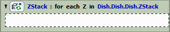
Figure 1259.
 Assign Z-Stack to Point/Well/ND Acquisition
 Every XY position (well, row of wells, column of wells) can have unique Z stack parameters after using this task. Scan a wider Z stack over the wells selected by the analysis. | Requires: Task: Z-Stack > Device: Stage Z |
 ND Acquisition
 Loop over Points
 Loop over Wells
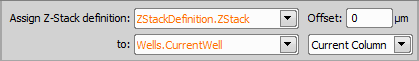
Figure 1260.
 Move to Z-Stack home
 Moves the Z drive to the home position of the selected Z stack definition. | Requires: Device: Stage Z |

Figure 1261.
Choose your Z-stack definition from your current job.
 Set Z Speed/Accuracy
Sets the stage Z speed so that different speeds can be used throughout the job. Use a slower Z speed to prevent the sample shift and get stability for the PFS during acquisition. Then use faster speed when changing samples to reduce the total acquisition time. | Requires: Module: |
Select the position to which the Piezo Z drive moves. The second Z drive compensates for this movement to stay on the same plane. If the Custom option is selected, an exact Z position can be entered into the field. Range displays the possible Z values falling into the current range of the device.
 Capture Continuous Z Stack
 (requires: JOBS) (requires: Local Option)
This task is mainly used for finding the bottom and top of a sample. It performs a Z-stack acquisition using continuous movement of the Z drive. This acquisition is very fast, but the Z coordinates are not so accurate (especially on the edge of the Z-stack) making the data not suitable for measurement or deconvolution. We have a sample with an organoid that is randomly positioned within a very large Z range. This task allows us to quickly scan the entire range, roughly detect where the organoid is, and then capture it using a precise Z-stack. Unlike autofocus, which finds only a single sharp plane, this approach determines the Z range where the organoid is located. High Z accuracy is not required in this use case. | Requires: Device: Stage Z |
Name of this task.
Specify the Z-Stack definition.
If checked, the acquisition images are saved.