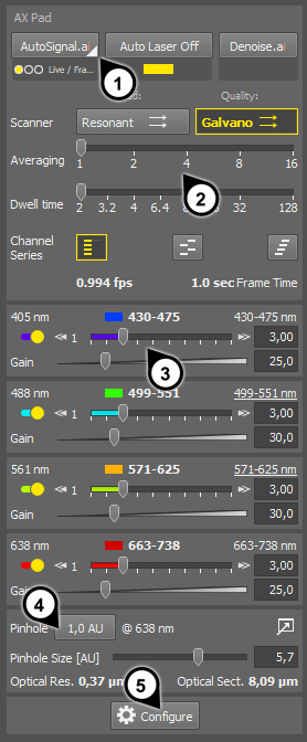
Figure 187. Ax Pad
Such as:
When this function is enabled, the system automatically performs AI processing on the live image and sets values of laser power and gain automatically. Before you run it, select properties of the sample by the button.
Laser power limits for each option can be set via the  Configure window. See AutoSignal.ai.
(requires: AX-SHR)
Automatic stopping of lasers. When the observation parameters such as XY stage position, focus, or brightness of the image do not change for some time, the system automatically stops laser emission and the acquired image is displayed as a still image.
Indicates SNR ratio of of each channel as a color rectangle. Green = high SNR, red = low SNR.
Caution
If SNR is low (red rectangle), the Denoise.ai function may produce unpredictable results.
Note
The Averaging option on the  AX Pad panel is always respected by the AI processing functions.
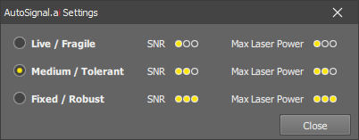
Figure 188. AutoSignal.ai options
Select the scanner to be used. The icon on the button indicates the selected scan direction (mono-directional, bi-directional).
Faster acquisition, lower image quality.
Slower acquisition, maximal image quality.
The scanning is performed several times and the pixel values are averaged / integrated which reduces image noise. Leave it low for a faster frame rate. Optionally the noise reduction technique can be changed to Integration in the device settings. In such case, the frames are added to each other, not averaged.
Acquisition speed defined by the time spent on one pixel. Longer times improve image quality. Dwell time is analogous to exposure time on cameras.
Note
This option is available with the galvano scanner only.
If the Show on Pad option is selected in the experiment setup, the buttons representing different channel series modes are displayed in the panel. You can quickly switch between them.
See Lasers and Detectors.
Tip
The frame rate and frame duration values are displayed at the bottom of this section. Try change the scanning settings and see how it affects these values.
(requires: MP)
This switch appears if a light path containing the NDD detector is selected. It sets gains of the PMTs to 0 in order to prevent their damage when opening the NDD detector. Whenever the user leaves an NDD light path, Protect NDD is applied automatically.
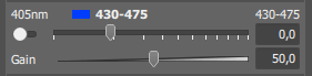
Figure 189. Channel settings, laser is OFF
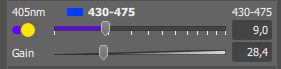
Figure 190. Laser is ON
Move the first slider to adjust laser power. Use the switch on the left to turn the laser on or off. You can also click the buttons in the “quick channel selection” section to enable or disable the whole channel. Try to keep the laser power as low as possible so that the sample does not bleach too quickly.
LUD-S lasers
LUD-S lasers are controlled in three separate ranges: <0,1>, <1,10>,<10,100>. Use the arrow buttons to switch between them.
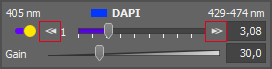
Figure 191. LUD-S laser with multi-range power control
MP
In a multiphoton experiment, a single IR laser can be used to capture multiple color channels. In such case, the laser power sliders and the ON/OFF switches are synchronized across the channels.
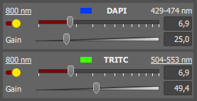
Figure 192. IR laser used for two channels
Note
Stimulation pads (Ax, GalvoXY) can show exclamation marks over the laser lines indicating that the laser does not pass through one of the mirrors on its light path defined in the current configuration.
This slider adjusts the multiplication factor of the signal from the detector. Increasing the gain makes the image brighter but also intensifies image noise.
The specified intensity value will be subtracted from all pixels of the channel, it reduces noise. You can display or hide the Offset option in the settings window - the Acquisition tab.
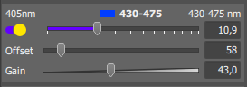
Figure 193. Offset slider displayed
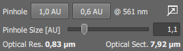
Figure 194.
Click the shortcut button to reset the pinhole size to the default value specified in the Configure window. The wavelength used to calculate the size of the AU (airy unit) is displayed next to the buttons, it can be changed in the settings window as well.
Note
One or two pinhole size buttons can be displayed here. To display the second button, click the  button and specify a non-zero value in the Custom Position field.
See Pinhole.
Move the slider to adjust the pinhole size.
Current optical resolution of the system.
Note
To achieve optimal resolution of an image, the Pixel size setting in the AX Scan Area panel should be 2.3 times smaller than the optical resolution (= Nyquist resolution).
Thickness of “Optical Section” indicates the FWHM (full width at half maximum) of z airy disk.
(requires: MP)
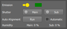
Figure 195.
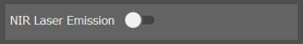
Here you can control the IR pulse lasers. You can select to hide this section in the options (AX-MP)
Click and hold the switch for 3 seconds to turn the IR pulse laser ON/OFF. The color indicator on the right will start blinking until the laser gets stable.
Mechanical shutters control whether the laser(s) shine to the light path.
This is reserved for the variable-wavelength laser.
It is important to run alignment every time the wavelength of the laser is changed.
If selected, automatic XY shift alignment will be performed after the IR laser wavelength is adjusted.
Click this button to run automatic alignment at once.
Some lasers can report humidity. If the value is displayed in red color, there may be a problem with the IR pulse laser body. In such case, stop using the IR pulse laser and immediately contact the supplier.
(requires: NSPARC)
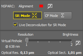
Figure 197.
Here you can select the NSPARC detector mode.
If the color indicator is red, alignment is needed. Click on the button to enter the Configure window directly on the NSPARC tab. If the alignment has been finished successfully, the indicator is green.
See NSPARC.
Super resolution mode which achieves better image quality (optical resolution). Precise alignment is needed. In this mode, an algorithm calculates the resulting value from the 5x5 array.
Confocal or Multi-photon mode. In this mode, the resulting pixel value is calculated as a sum of the 5x5 array values. Alignment is not needed.
Select this option to perform real-time deconvolution on the live data when in the SR Mode. Even more details should be visible.
The actual pinhole is not used with the NSPARC detector. Instead, there is an adjustable zoom unit which which has a very similar effect on the image. Adjust the settings according to your preference between image resolution and brightness.
(requires: MP) In multi-photon mode, the button appears. If pressed, maximum of available light will be transmitted.