 Binary processing
Cell Processing

Basic
Morphology
Circular Morphology
Linear morphology
Detect
Region growing
Skeleton
Connectivity
Filter objects
Remove objects
Insert objects
Colors & Numbers
Transformations
JavaScript
Connect slices
This node is used to process cell and nuclei binaries. Cells without nucleus are removed. Only the largest nucleus in every cell is kept. Both binaries are given IDs so the cell and its nucleus has the same ID. This node processes binaries for the use in Cell measurement.
Filter out cells based on the cell nucleus area ratio.
Removes binary objects which cannot contain a circle of the specified Radius.
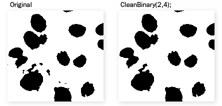
Figure 943. Example
Figure 944.
Removes those binary objects that cannot contain a circle of specified radius.
Click the button to change the structuring element used for this operation. See Structuring Element = Kernel = Matrix.
Number of iterations.
 Reset
Reset Sets the dialog default values.
Removes small holes from the current binary image.
Fills all holes in the binary image which would be destroyed by Erosion of the specified parameters.
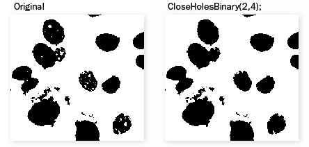
Figure 945. Example
Click the button to change the structuring element used for this operation. See Structuring Element = Kernel = Matrix.
Number of iterations.
Reset Sets the dialog default values.
Morphological closing performs Dilation followed by Erosion (see Binary processing > Morphology > Close). Close operation is restricted by Parent (Ref) binary and will connect only children in same parent. Node can be used, for example, to connect multiple nuclei in cell.
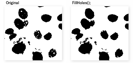
If the connected binary does not contain any binary information, it is fully filled.
Separates binary objects into multiple smaller objects. The higher the Count, the fewer objects will be separated.
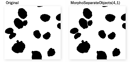
Figure 947. Example
Morpho Separate Objects dialog box appears.
Figure 948.
Click the button to change the structuring element used for this operation. See Structuring Element = Kernel = Matrix.
Number of iterations.
Separates bright objects from the background based on both the binary layer and the intensity. The object detection can be adjusted using the Peak strength parameter.
Separates dark objects from the background based on both the binary layer and the intensity. The object detection can be adjusted using the Peak strength parameter.
Smooths binary image contours.
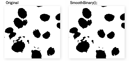
Figure 949. Example
Note
The algorithm is based on weak morphology (combination of appropriate convolution followed by threshold). This operation removes small objects and cuts narrow protrusions. On the other hand it fills in small holes and thin gulfs.
Figure 950.
It is possible to define the strength of the function by specifying the number of iterations.
Smooths every binary pixel using circle of the specified radius.
Reset Sets the dialog default values.
Smooths the contours of each binary object present in the connected binary image and correctly separates objects from one another.
Smooths every binary pixel using circle of the specified radius.
Morphological opening performs Erosion followed by Dilation. This has the effect of clearing all objects which are too small with respect to the specified parameters. Larger structures are not significantly affected.
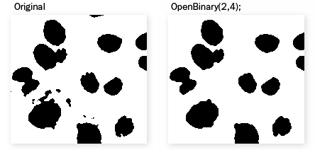
Figure 951. Example
Click the button to change the structuring element used for this operation. See Structuring Element = Kernel = Matrix.
Number of iterations.
Reset Sets the dialog default values.
Morphological closing performs Dilation followed by Erosion. It fills all holes in objects which are too small with respect to the specified parameters. Closely neighboring objects get connected.
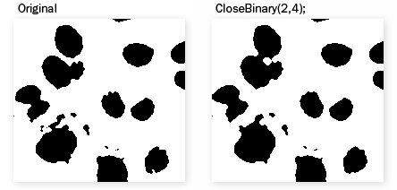
Figure 952. Example
Figure 953.
Click the button to change the structuring element used for this operation. See Structuring Element = Kernel = Matrix.
Number of iterations.
Reset Sets the dialog default values.
Erosion sets each pixel to the value computed as minimum from all pixels in the matrix. Erosion shrinks objects and removes small ones. A non-convex object can split into several parts.
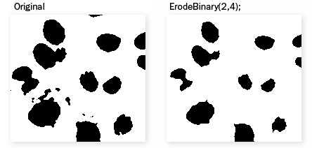
Figure 954. Example
Click the button to change the structuring element used for this operation. See Structuring Element = Kernel = Matrix.
Number of iterations.
Reset Sets the dialog default values.
See Also
Binary > Dilate
Dilation sets each pixel to the value computed as maximum from all pixels in the matrix. Dilation expands objects and structures in binary image. Neighboring objects are connected and small holes are filled.
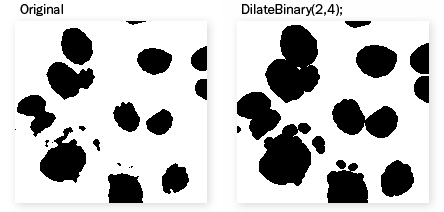
Figure 955. Example
Click the button to change the structuring element used for this operation. See Structuring Element = Kernel = Matrix.
Number of iterations.
Reset Sets the dialog default values.
Performs Erosion followed by Dilation. This has the effect of clearing all objects which are too small with respect to the specified parameters. Larger structures are not significantly affected.
Morphological closing performs Dilation followed by Erosion. It fills all holes in objects which are too small with respect to the specified parameters. Closely neighboring objects get connected.
Euclidean erosion sets each pixel to the value computed as minimum from all pixels within the specified Radius. This will shrink/remove binary objects in the image.
Pixel neighborhood specifying source-data for the current function.
Euclidean dilation sets each pixel to the value computed as maximum from all pixels within the specified Radius. This will enlarge/merge binary objects in the image.
Pixel neighborhood specifying source-data for the current function.
Removes binary objects that cannot contain a sphere of the specified radius i.e. objects smaller than Radius.
Pixel neighborhood specifying source-data for the current function.
Fills all holes which cannot contain a sphere of the specified radius i.e. holes smaller than Radius.
Pixel neighborhood specifying source-data for the current function.
Performs morphologic opening on binary image using the selected linear matrix. The choice of the structuring element defines the direction in which the binary image will be affected. See Binary > Open.
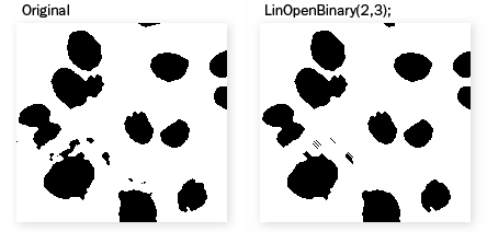
Figure 956. Example
Click the button to change the structuring element used for this operation. See Structuring Element = Kernel = Matrix.
Number of iterations.
Reset Sets the dialog default values.
Highlights structures with a linear pattern using the Linear Open function in the Z direction. Please see Image Processing > Linear Morphology > Linear Open.
Performs morphologic closing on binary image using the selected linear matrix. The choice of the structuring element defines the direction in which the binary image will be affected. See Binary > Close.
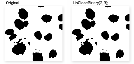
Figure 957. Example
Click the button to change the structuring element used for this operation. See Structuring Element = Kernel = Matrix.
Number of iterations.
Reset Sets the dialog default values.
Highlights structures with a linear pattern using the Linear Close function in the Z direction. Please see Image Processing > Linear Morphology > Linear Close.
Performs erosion on binary image, it removes a layer of pixels in the direction of the selected matrix. See Binary > Erode.

Figure 958. Example
Click the button to change the structuring element used for this operation. See Structuring Element = Kernel = Matrix.
Number of iterations.
Reset Sets the dialog default values.
Highlights structures with a linear pattern using the Linear Erode function in the Z direction. Please see Image Processing > Linear Morphology > Linear Erode.
Performs dilation on binary image, it adds a layer of pixels in the direction of the selected matrix.
See also Binary > Dilate.
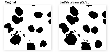
Figure 959. Example
Click the button to change the structuring element used for this operation. See Structuring Element = Kernel = Matrix.
Number of iterations.
Reset Sets the dialog default values.
See Also
Binary > Erode
Highlights structures with a linear pattern using the Linear Dilate function in the Z direction. Please see Image Processing > Linear Morphology > Linear Dilate.
Calculates and marks the centroid of the objects found in the connected binary image.
Converts binary objects to their centroids. Select the method of determining centroid positions.
Figure 960.
If bright/dark areas dominate aside of the centroid position calculated from just the binary layer, the centroid will be shifted in that direction.
Connects binary objects which are closer to each other than the specified distance by a thin line.
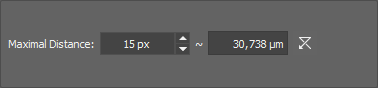
Figure 961.
Set the maximal distance of two objects to be connected.
Transforms binary image to its 1 pixel wide contour.
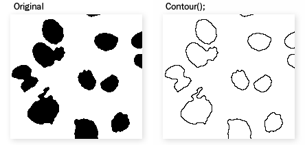
Figure 962. Example
This function expands non-convex binary image objects to their convex boundaries.
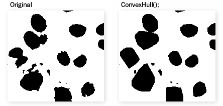
Figure 963. Example
Displays the distance of each object pixel to the nearest boundary (background pixel) as an intensity value.
The resulting color image is a floating point image.
Figure 964. Example
Click the button to change the structuring element used for this operation. See Structuring Element = Kernel = Matrix.
Creates a binary layer with marked geodesic centers.
A Geodesic Center is a point within the object, such that the sum of its distances to every other point in the object is minimal. For convex objects, it corresponds to the center of gravity. The algorithm used to calculate the geodesic center is approximate.
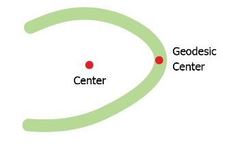
Figure 965. Illustration showing the geodesic center of the green object.
Note
This operation on one object may result into multiple centers. Same as if the you use the Binary processing > Morphology > Open node using the  matrix.
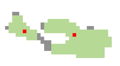
Figure 966.
Original object.
The object after Binary processing > Morphology > Open.
Geodesic centers.
This command creates the granulometry image from the binary image.
Marks objects with homotopic marks. Homotopic marking is a sequential homotopic thinning. It is used for marking objects. A filled object (with no holes) is transformed to a single point. Every hole leaves a closed contour.

Figure 967. Example
Replaces each binary object by its inscribed circle. Inscribed circle is the largest circle that can be contained in the object.
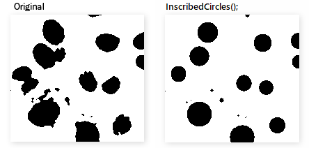
Figure 968.
This command creates medial axis from the current binary objects.
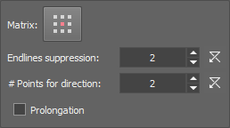
Figure 969.
Specifies a structuring element for finding the distance to the boundary.
Determines the axis shape. The higher is the value, the more simple is the shape.
Determines how many points are used to calculate the direction of the medial axis prolongation. Values are larger than 2.
Determines whether the medial axis prolongation is used or not.
Sequentially removes end-points from binary image. This function is used for simplification of skeletons by removal of branches. Closed contours remain unchanged.
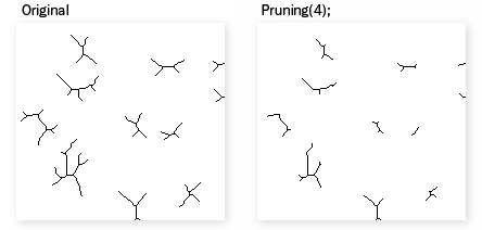
Figure 970. Example
The following window appears.
Figure 971.
Specifies the number of iterations; 0 stands for complete removal of branches. This command is mainly used for skeletonized images.
Sequentially erodes binary image, but leaves small areas which would completely disappear in the next erosion.
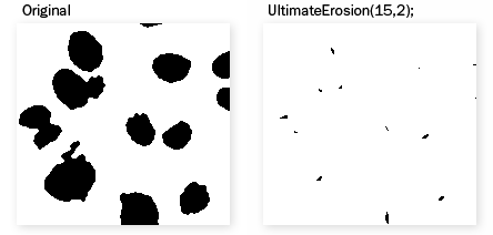
Figure 972. Example
Click the button to change the structuring element used for this operation. See Structuring Element = Kernel = Matrix.
Set 1 for maximum possible erosion. Any number higher than 1 will do fewer erosions and preserve bigger parts of each object.
Grows each binary object by a circle (2D) / sphere (3D) of the specified radius. Objects will not be merged together.
Pixel neighborhood specifying source-data for the current function.
Grows objects in the image until the fraction of the total object area to total image area is the same as the parameter Area Fraction.
Fraction of total object area to total image area.
Grows each binary object up to the specified intensity. Objects will not be merged together.
will grow from maximum intensity to the specified intensity.
will grow from minimum intensity to specified intensity.
Creates zones of influence by the fast 'pipe of pixels' algorithm. Performing this command, the ZonesOfInfluenceFast is called and appended to the list of executed functions.
For every binary object in the connected image this node creates an interior circle object and a ring around it. It is guaranteed that the corresponding circle and ring have the same object ID and that the number of circles and rings is equal. Places where the circle or ring should disappear both are removed in order to maintain the same IDs. In case it breaks in more objects the biggest is taken and the others are discarded. Circle can be restricted by adding a hole (width of the hole is measured from the circle boarder). Adjust the width of each feature by typing a value into the edit box or using the arrows.
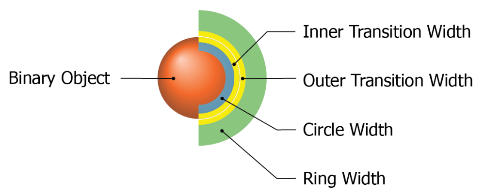
Figure 973. Features of the Circle & Ring node.
Dilates a binary image without changing the number of objects - it is a homotopical transformation.
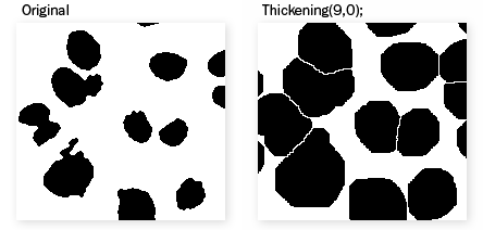
Figure 974. Example
Specifies the number of iterations, i.e. number of layers being added to each object. Parameter 0 performs ultimate dilation (neighboring objects touch each other).
Performs the watershed (flooding) algorithm starting from the connected binary objects. The flooding is based on image pixel intensities.
Defines the direction of flooding - from high intensities (From Bright Regions) or from low intensities (From Dark Regions).
Creates zones of influence by drawing four connectivity borders. For each pixel of a border between two objects, the distance to both objects is the same.
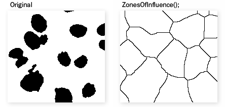
Figure 975. Example
Makes a skeleton of the binary image. The current binary image is dilated and then intersected by reference binary image. This step is repeated until there is no difference in the sequence of consecutive images. The current image may be e.g. erosion of the original image copied to reference binary image. In this case the function reconstructs only bigger objects and rejects smaller objects.
Skeleton is a representation that largely preserves extent and connectivity of original binary objects, while pruning most of original pixels.

Figure 976. Example
The purpose of this command is to create 1pixel seeds out of a skeletonized binary image. This function serves for automatic recognition of the intersection points of single-pixel lines.
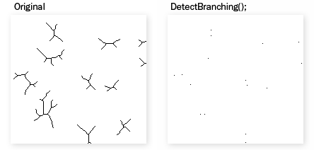
Figure 977. Example
Purpose of this command is to create 1pixel seeds out of a skeletonized binary image. It preserves only ending points of the skeleton and clears all other pixels.
On a skeletonized binary image, branches (free endings) shorter than the defined length will be removed.
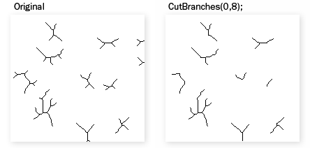
Figure 978. Example
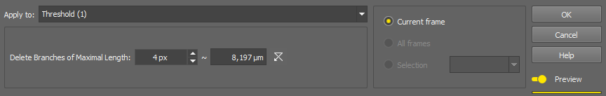
Figure 979.
Shorter branches will be deleted.
On a skeletonized image, connects branch peaks. Set sensitivity of the function in the window:
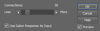
Figure 980.
Set sensitivity of the function. The higher the more connections will be created.
Apply Gabor edge detection to the image before evaluating the edge strength.
On a skeletonized image, circular (enclosed) objects with equivalent diameter (eqdia) smaller than the defined value will be deleted. You do not necessarily want to delete small objects but the ones which are mis-detected.
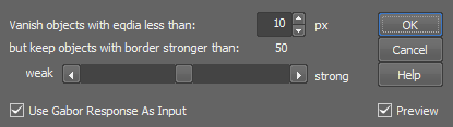
Figure 981.
Objects with eqdia smaller than this value will be erased.
Set the threshold value for deletion. Binary objects containing a strong-enough edge in the color image will be preserved regardless of the eqdia value.
Apply Gabor edge detection to the image before evaluating the edge strength.
Shortens each branch of a skeleton by the specified amount in pixels.
This operation adds pixels to ensure that each pixel which is only 8-connected will become 4-connected. 4-connected pixels are those connected vertically or horizontally, but not diagonally.
See Connectivity.
This operation removes pixels to ensure that each pixel which is only 4-connected will become 8-connected. 8-connected pixels are those either vertically, horizontally, or diagonally. See Connectivity.
Filters the connected objects using a filter or multiple filters. Set a filter by selecting the filtering Feature, setting the Comparator and the numeral Value. To add another filter, click  New Filter.... To delete a filter, click
  .
.
Removes any binary object not meeting the specified condition. Objects having the specified feature outside of the specified range will be removed.
Selects binary objects from the binary image which are present in input table.
Selects the number of largest objects specified in the Count of objects box.
Deletes binary objects from the binary image which are present in input table.
Removes binary objects touching the image border.
Removes binary objects touching the image frame. Select units and set the width, height and position of the frame. Then choose a mode defining which objects are to be removed.
Draws a circle to the binary image.
Coordinates of the center of the drawn object.
Radius of the circle in Units.
Closed shapes can be either filled or hollow. Select TRUE to fill the shape or FALSE to leave it hollow.
Select how to interact with the existing binary layer.
Clears the input binary image.
Performs logical OR between the binary layer and the drawn object.
Performs logical AND between the binary layer and the drawn object.
Subtracts the drawn object from the binary layer.
Select whether the coordinates/dimensions of the shape will be specified in pixels or in the image calibration units.
Draws an Ellipse to the binary image.
Coordinates of the center of the drawn object.
Length of the semi-major axis in Units.
Length of the semi-minor axis in Units.
Closed shapes can be either filled or hollow. Select TRUE to fill the shape or FALSE to leave it hollow.
Select how to interact with the existing binary layer.
Clears the input binary image.
Performs logical OR between the binary layer and the drawn object.
Performs logical AND between the binary layer and the drawn object.
Subtracts the drawn object from the binary layer.
Select whether the coordinates/dimensions of the shape will be specified in pixels or in the image calibration units.
Adds a rectangle frame to the connected binary layer. Define the frame by entering the distance from the image borders (Left, Top, Right, Bottom) with proper Units. Define whether the frame will be Filled or not and set the visualization Mode determining the interaction between the binary layer and the new frame.
Draws a line to the binary image.
Coordinates of the endpoints in pixels.
4 or 8, defines the way a line is drawn. See Connectivity.
Select how to interact with the existing binary layer.
Clears the input binary image.
Performs logical OR between the binary layer and the drawn object.
Performs logical AND between the binary layer and the drawn object.
Subtracts the drawn object from the binary layer.
Select whether the coordinates/dimensions of the shape will be specified in pixels or in the image calibration units.
Draws a line connecting centers of two largest binary objects in connected binary layer.
Select how center of object is calculated - Center, Centroid (Light signal), Centroid (Dark signal).
Select type of line (Segment Line, Line, Perpendicular).
Number of parallel lines.
Distance between neighboring parallel lines.
Line offset in perpendicular direction.
4 or 8, defines the way a line is drawn.
Select how to interact with the existing binary layer.
Clears the input binary image.
Performs logical OR between the binary layer and the drawn object.
Performs logical AND between the binary layer and the drawn object.
Subtracts the drawn object from the binary layer.
Draws multiple parallel lines to the binary image.
Distance between two adjacent lines defined in Units.
Angle of the lines
4 or 8, defines the way a line is drawn. See Connectivity.
Select how to interact with the existing binary layer.
Clears the input binary image.
Performs logical OR between the binary layer and the drawn object.
Performs logical AND between the binary layer and the drawn object.
Subtracts the drawn object from the binary layer.
Select whether the coordinates/dimensions of the shape will be specified in pixels or in the image calibration units.
Draws a rectangle to the binary image.
Coordinates of the top-left corner of the rectangle in Units.
Rectangle dimensions in Units.
Closed shapes can be either filled or hollow. Select TRUE to fill the shape or FALSE to leave it hollow.
Select how to interact with the existing binary layer.
Clears the input binary image.
Performs logical OR between the binary layer and the drawn object.
Performs logical AND between the binary layer and the drawn object.
Subtracts the drawn object from the binary layer.
Select whether the coordinates/dimensions of the shape will be specified in pixels or in the image calibration units.
Draws a grid of markers to the binary image.
Select shape for the grid markers.
Select whether the coordinates/dimensions of the shape will be specified in pixels or in the image calibration units.
Distance between two adjacent markers defined in Units.
Select how to interact with the existing binary layer.
Clears the input binary image.
Performs logical OR between the binary layer and the drawn object.
Performs logical AND between the binary layer and the drawn object.
Subtracts the drawn object from the binary layer.
Draws one marker to the binary image.
Select the marker shape.
Coordinates of the marker in Units.
Select whether the coordinates/dimensions of the shape will be specified in pixels or in the image calibration units.
Select how to interact with the existing binary layer.
Clears the input binary image.
Performs logical OR between the binary layer and the drawn object.
Performs logical AND between the binary layer and the drawn object.
Subtracts the drawn object from the binary layer.
Insert arbitrary number of circles from a table into the binary image.
Insert arbitrary number of fixed circles from a table into the binary image.
Insert arbitrary number of lines from a table into the binary image.
Draws a plane to the binary volume. Plane is defined by coordinates of any point belonging to it, by the space orientation and mode of interacting with the existing layer. Select Units and Coordinates of any point belonging to the plane. Then choose a parallel Plane and Mode for interacting with the existing layer.
Mode
Clears the input binary image.
Performs logical OR between the binary layer and the drawn object.
Performs logical AND between the binary layer and the drawn object.
Subtracts the drawn object from the binary layer.
This function displays the binary objects in several different colors. The algorithm is optimized so that two neighboring objects would never display in similar colors.
Assigns any color to any value of the selected source column used from the connected table.
In the following scenario, positive and negative numerical values are divided into two intervals labeled with different colors. Therefore all negative values will be assigned a red color and all positive values will be assigned a green color.
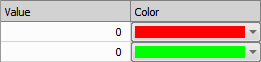
Figure 982. Positive and negative values divided into two intervals by number 0.

Figure 983. Example of the color assignment defined above.
Table source column.
Table binary ID column.
 Add bin (after selected)
 Adds a new bin to the table.
 Remove selected bin
 Removes the selected bin from the table.
 Remove all bins
 Removes all bins from the table.
 Generate bins automatically
 Opens the Generate Bins window where it is possible to set the parameters generating the bins automatically. Please see the description here: Generate bins automatically.
 Paste from clipboard
 Inserts the table data from clipboard into the frequency table.
 Copy colors to clipboard
 Copies the full table to clipboard.
If you have deleted some objects , this command renumbers all the remaining ones so that numbering starts from 1 and is continuous. Only numbers greater than the deleted ones are renumbered.
Renumberes the binary objects with values taken from the the connected table. Source column has to be specified.
Renumbers the binary objects of detected TMA (Tissue microarray) cores. Select Skip Gaps to not include numbers of missing cores in indexing (so binaries will be numbered from 1 to N, where N is count of binary objects).
This node automatically detects columns and rows of grid of TMA cores. Then it assigns new indexes so that cores in the upper row have smaller indexes than cores in the lower row. In each row, cores are indexed from left to right. Numbers of missing cores are not used (for example, if you have 10 cores in a 4x3 grid, core in the bottom right corner (if not missing) will always have an index of 12).
For good results cores should be laying in a square grid which is not rotated.
Note
This node can be used on any binary objects laying in a square grid (not just TMA cores).
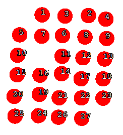
Figure 984. TMA Renumbering Example (before)
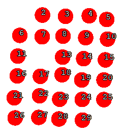
Figure 985. TMA Renumbering Example (after)
Adds a border to the binary layer. Define the Top, Left, Right and Bottom borders and set the Value which will be added to the borders.
Crops the connected binary image to the specified width and height [px]. Shift the cropping rectangle by filling the Start x and Start y position.
Crops to the center of the connected binary image by the specified width and height [px].
Shrinks the source binary image so that it fits into a square with a given size. Aspect ratio of the binary is maintained as well as all other properties.
Number of pixels of the longer side of the image.
Flips the source binary horizontal and/or vertical. Simply check Horizontal flip or Vertical flip to flip the image in the particular direction.
Flips the source 3D binary horizontal and/or vertical. Simply check Horizontal flip or Vertical flip to flip the image in the particular direction.
Shifts the connected binary image horizontally (X Offset) or vertically (Y Offset). Area shifted outside the image borders can be placed to the opposite side if Rotate values around image borders is checked.
Resizes the binary image by a given ratio.
Ratio in X axis.
Ratio in Y axis.
Resizes the source binary image (A) so that it has the same size as the reference binary image (B).
Rotates the connected binary image by the specified angle.
Connects 2D slices from subsequent frames into the 3D binary. Most of the time, it is not necessary to use this node. All 3D binary processing nodes do this operation automatically. Use it only when the final binary result is 2D and is desired to be 3D. This node does not change the underlying binary data.