Spot Detection

Segmentation
3D Spot Detection
3D Processing/Morphology
Mask
Detect
Linear Morphology
Advanced Morphology
Skeleton Morphology
ND Processing
Click in the middle of an object.
Scroll the mouse wheel. A preview of the future binary layer dynamically appears in the image while you are scrolling the mouse wheel. This defines the approximate size of detected object. Similar objects throughout the image are being detected.
Click the secondary mouse button when you are satisfied with the preview. A binary layer is created.
Smart threshold can be performed repeatedly. The new data are added to the original binary layer.
Create at least two binary layers each representing certain type of scene. E.g.:
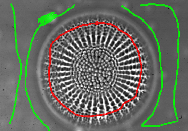
Figure 1824. Graph Cut - User Defined Binaries
Run the Binary > Segmentation > Graph Cut Segmentation command.
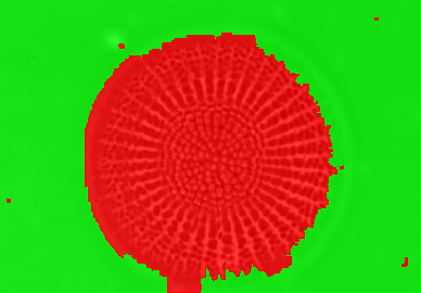
Figure 1825. Graph Cut - Result
Displays/hides all binary layers. Use the O keyboard shortcut.
Synchronizes binary layers with their attached channel.
Note
If the Sync button is on, the created binary layer is automatically attached to the selected image channel. This works for multi-channel images, not for RGB images. For RGB images, the created binary layer is always global (not attached to any color component).
Creates a new empty binary layer.
Layer3: displayed (checked box) and selected (highlighted) for binary drawing.
Layer2: displayed (checked box), but not selected for binary drawing.
Layer1: hidden (unchecked box), not selected for binary drawing, assigned to the FITC channel.
Select the First Layer and the Second Layer from the combo boxes. Binary operations will be performed between these two layers.
Select the logical operation to be performed. You can also select the Preview check box to view the result of the operation in the image window.
Now choose where the result will appear in the Insert Result into area. You can select to overwrite the data in the first or second layer with the data of the result or to create a new layer containing the result. If so, type the name of the new layer in the edit box.
Click to confirm the action.
Enter a name for a user-defined structuring element.
Click to the Layout boxes to define the kernel.
Confirm it with the button.
Use the Binary > Skeleton Morphology > Skeletonize command on an existing binary layer. One pixel lines are created.
Run Binary > Skeleton Morphology > Detect Branching on Skeleton to leave pixels just where the line was branching.
Use the Binary > Skeleton Morphology > Skeletonize command on an existing binary layer. One pixel lines are created.
Run Binary > Skeleton Morphology > Detect Branching on Skeleton to leave pixels just on the lines endings.

Note
If you are running NIS-Elements with Local Options (Step 2), please see Define Threshold for the appropriate dialog description.
Thresholds the image and creates a binary layer. Please see Thresholding.
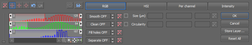
Figure 1819.
You can create multiple binary layers within one document. Use the View > Analysis Controls > Binary Layers  control window to manage all binary layers at once.
This button opens a dialog window, which saves the currently thresholded binary as a new layer. Enter Name of the new layer. Set it as visible or not, and specify its color.
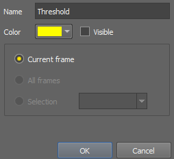
Figure 1820.
Apply the command to the whole image sequence, the selected dimension or just the current image frame. See ND2 Files Processing.
(requires: Local Option)
Thresholds the image and creates a binary layer. Please see Thresholding.
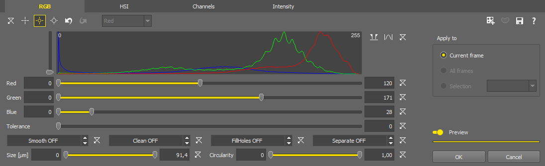
Figure 1821.


 Picking tools
 Select a picking tool and click on objects in the image you wish to detect. Color values of each of the clicked pixel(s) are used to adjust the low and the high threshold values so that the clicked pixel would stay inside the thresholded interval. To reset the threshold values back to default click  .
.
This drop-down menu specifies which channel is thresholded when the Channels mode is selected.
 Custom Range
 Zooms to the current range.
 Actual Range
 Zooms to the minimum - maximum range.
 Full Range
 Zooms to the full domain.
These binary processing functions can be activated and their value adjusted using the arrows or directly by typing the value into the edit box. Fill Holes processing can only be turned on/off whereas the values of other processings are applied as a radius in µm or px.
Filter the detected binary objects using the Size or Circularity restriction filters.
 Create New Binary Layer
 You can create multiple binary layers within one document. Use the View > Analysis Controls > Binary Layers control window to manage all binary layers at once.
 Full Image/Use ROI
 When turned on, this function thresholds only in the ROI area.
 Save/Load Threshold Settings...
 Saves/loads the settings of this dialog window to/from a .threshold file.
 Open Help
 Opens the help document.
Apply the command to the whole image sequence, the selected dimension or just the current image frame. See ND2 Files Processing.
If turned on, the thresholding settings are shown directly in the image once the progress indicator below the switch is fully displayed.
Confirms the thresholding settings and closes the dialog window.
Closes the dialog window without applying any thresholding settings.
Segments color image according to threshold levels for RGB.
This function detects pixels with RGB intensities within the range specified by the Binary > Define Threshold command. Current binary image is the result of the transformation.
See ND2 Files Processing for description of common settings.
Performs automatic threshold of the current image.
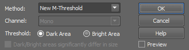
Figure 1822.
Select one of the available algorithms. Try it on your specimen, to see which one is best for your images:
For more details please see en.wikipedia.org/wiki/Otsu%27s_method.
For more details please see en.wikipedia.org/wiki/Maximally_stable_extremal_regions.
Select an image channel to be processed.
Choose whether you want to detect dark or bright objects.
Auto threshold works well on images with balanced intensities (bright and dark areas have similar size). If the intensities are not balanced, they should be compensated using this function.
This command is designed to threshold objects of similar size and average pixel intensity.
This function opens the Spot Detection dialog window in the Bright Spots mode. It is used mainly for detecting circular objects with similar sizes. For more information please see Spot Detection.
Note
General analysis 3 spot detection uses the Different Sizes object detection method.
This function opens the Spot Detection dialog window in the Dark Spots mode. It is used mainly for detecting circular objects with similar sizes. For more information please see Spot Detection.
Note
General analysis 3 spot detection uses the Different Sizes object detection method.
Opens the Homogeneous Area Detection dialog window suitable for detecting objects on a homogeneous background and objects which are difficult to segment. Advantage of this function is that the objects do not need to be distinguished by intensity because the function works with edges. This is useful especially for DIC and phase-contrast images.
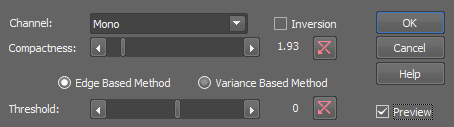
Figure 1823.
Channel on which the detection will be performed.
Inverts the detected binary.
The higher the value, the more compact object border is created.
Try which method works best for your image. In some cases, the Variance Based Method may bring better results.
Use this slider to find the optimal threshold for your objects.
Apply the command to the whole image sequence, the selected dimension or just the current image frame. See ND2 Files Processing.
Implements the so-called “Graph cut algorithm” to enable segmentation of samples where it is impossible to use thresholding or other segmentation methods.
Define Measurement Sequence panel is used for the preparation of advanced measurements which are organized in the Measurement Explorer and executed by the Measurement Sequence Run. A set of measurement tools is arranged in five groups enabling to easily define any complex measurement.
This command performs automatic wound detection. It tries to detect homogeneous areas within the image and save the results into a binary layer. It can be well used for analysis of “wound healing” on time-lapse images.
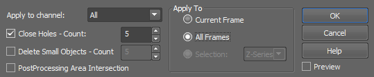
Figure 1826. Dialog on a Z ND2 image
Select a channel to be processed.
On multi-channel images, all channels are processed separately and the resulting binary layers are merged into one.
On RGB images, the intensity component is processed. Intensity = (R+G+B)/3.
Use the Close Holes command to fill holes in the detected objects. Specify how many times the command will be run.
Delete the smallest objects. Specify how many times the command will be run.
Available on non-timelapse images.
This selection enables you to perform logical AND with the previous result (binary layer). Only pixels which were detected in both runs will remain in the binary layer.
Available on timelapse images.
In most cases the Auto threshold function works fine. If you need to adjust your wound area detection threshold more precisely, use the Manual slider.
See ND2 Files Processing.
Select this option to preview the effect of the operation on the current image.
This command finds object edges in the image and marks them by a binary layer.
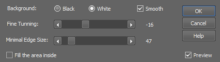
Figure 1827.
Select color of the image background.
Select this option to make the detected edges smoother.
An automatic algorithm finds the edges in the image. If the image is not optimal, you may adjust the result by moving this slider. Check the Preview box to see how it influences the binary layer.
Specify the minimum edge length in pixels. Only objects with longer edge will be detected.
Select this option to preview the effect of the operation on the current image.
Fills the area inside the edges with the binary layer.
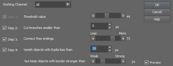
Figure 1828.
Performs the segmentation of binary layer using tight borders detection.
Choose the working channel for the detection (the options depend on the type of the image).
Choose which step will be used in the detection (Threshold Value, Cut Branches, Connect Free Endings, Vanish Objects).
Apply the command to the whole image sequence, the selected dimension or just the current image frame. See ND2 Files Processing.
Select this option to preview the effect of the operation on the current image.
(requires: 3D Measurement)
This command thresholds 3D objects. Following window appears:
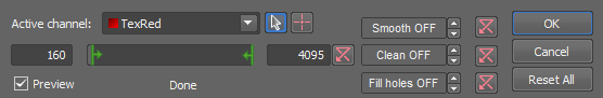
Figure 1829.
The point is to determine which pixels will and which will not be included in the binary layer and thereby distinguish objects to be analyzed from background. You can define the threshold on an active channel of the image which you can select from the pull down menu. Then move the sliders to define the limit values for selected active channel.
(requires: 3D Measurement)
This command detects bright circular objects within a 3D space. Please see Binary > Spot Detection > Bright Spots for further description.
Note
General analysis 3 spot detection uses the Different Sizes object detection method.
(requires: 3D Measurement)
This command detects dark circular objects within a 3D space. Please see Binary > Spot Detection > Dark Spots for further description.
Note
General analysis 3 spot detection uses the Different Sizes object detection method.
(requires: 3D Measurement)
Connects Z-stack slices of 2D binary objects into 3D binary objects.
(requires: 3D Measurement)
Performs morphological opening on 3D binary image. See also Binary > Open.
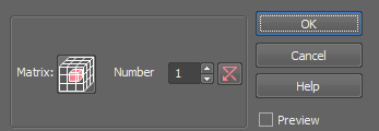
Figure 1830.
(requires: 3D Measurement)
Performs morphological closing on 3D binary image. See also Binary > Close.
Figure 1831.
(requires: 3D Measurement)
Performs morphological erosion on 3D binary image. See also Binary > Erode.
Figure 1832.
(requires: 3D Measurement)
Performs morphological dilation on 3D binary image. See also Binary > Dilate.
Figure 1833.
(requires: 3D Measurement)
Euclidean Open performs Euclidean Erosion followed by Euclidean Dilation. It clears all areas which cannot contain a circle/sphere of the specified radius.
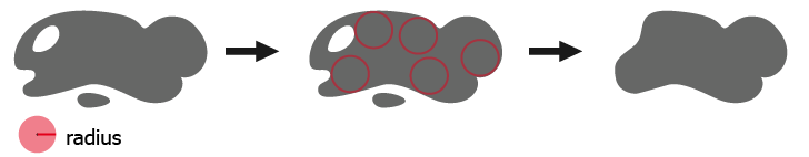
Figure 1834.
See Also
Binary > Open
(requires: 3D Measurement)
Euclidean Close performs Euclidean Dilation followed by Euclidean Erosion. It fills all areas of background which cannot contain a circle/sphere of the specified radius.
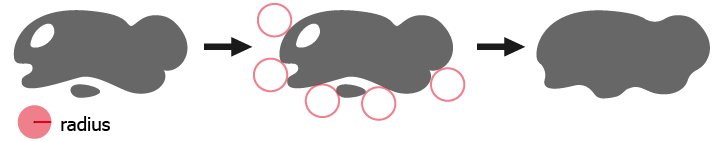
Figure 1835.
See Also
Binary > Close
(requires: 3D Measurement)
Euclidean erosion sets each pixel to the value computed as minimum from all pixels within the specified Radius. This will shrink/remove binary objects in the image.
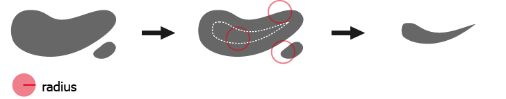
Figure 1836.
See Also
Binary > Erode
(requires: 3D Measurement)
Euclidean dilation sets each pixel to the value computed as maximum from all pixels within the specified Radius. This will enlarge/merge binary objects in the image.
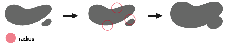
Figure 1837.
See Also
Binary > Linear Morphology > Dilate
(requires: 3D Measurement)
Grows each binary object by a circle (2D) / sphere (3D) of the specified radius. Objects will not be merged together.
(requires: 3D Measurement)
Removes small objects from 3D binary image. See also Binary > Clean  .
.
Figure 1838.
(requires: 3D Measurement)
Removes small holes from 3D binary image. See also Binary > Close Holes.
Figure 1839.
(requires: 3D Measurement)
Smooths binary image contours in 3D. See also Binary > Smooth.
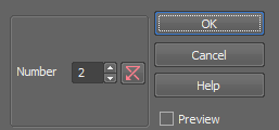
Figure 1840.
(requires: 3D Measurement)
Separates 3D binary objects. The lower the Number, the more borders separating the binary objects are introduced.
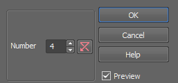
Figure 1841.
(requires: 3D Measurement)
Fills holes inside 3D binary objects present in the current volume. Holes touching image borders are not filled.
(requires: 3D Measurement)
Makes a skeleton of the 3D binary image.
(requires: 3D Measurement)
Creates 1pixel seeds out of a skeletonized 3D binary image. This function serves for automatic recognition of the intersection points of single-pixel lines.
(requires: 3D Measurement)
Creates 1pixel seeds out of a skeletonized 3D binary image. It preserves only ending points of the skeleton and clears all other pixels.
(requires: 3D Measurement)
This function expands non-convex 3D binary image objects to their convex boundaries.
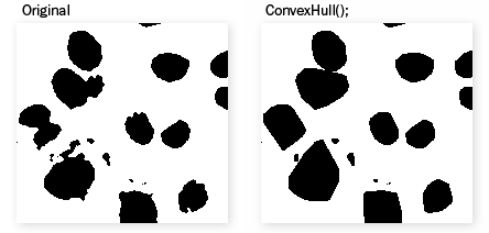
Figure 1842. Example
(requires: 3D Measurement)
This function performs distance transformation on a Z-stack of binary layers. The function calculates distance from the edge of the 3D binary inwards. For uncalibrated documents, pixel distance is used and Z distance is multiplied by 4. For calibrated documents, the distance is calculated in units used for the calibration, then multiplied by 10 and converted into integers. Float distance is not multiplied, µm distance is used instead.
See also Binary > Advanced Morphology > Distance Function and ND2 Files Processing for description of other settings.
(requires: 3D Measurement)
This command calculates and marks a centroid on binary image in 3D. Select which method is used to calculate the centroid. See also Binary > Detect > Centroids.
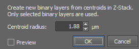
Figure 1843.
This command opens the binary layer(s) editor. Please see Binary Editor for detailed description of the tools.
(requires: Local Option)
Opens the Manual Segmentation toolbar. Tools for drawing the binaries are red, whereas tools for erasing are blue. Use the Tab button to switch between drawing and erasing. Set the thickness of the drawn elements using the Size drop-down menu or select an existing line thickness (can be different for drawing and erasing). The last chosen tool in drawing/erasing is remembered. Adjust the tools in the  Settings dialog. Once you start drawing a binary, a new toolbar above the image is shown and a new binary layer is created. You can add a new binary layer by clicking on the
  button. The drawn binaries are saved into the layer which is selected (highlighted). Checking the check box of the specific layer makes the layer visible in the image. The order of the layer buttons can be changed by dragging and dropping them.
Each layer can also be attached to an image channel. Simply right-click on the layer rectangle, select Attach To and choose a channel. The attached channel is indicated in the layer button. The button context menu can also be used to detach a layer from a channel (Detach from), remove the selected layer (Remove), rename it (Rename, or use double-click) or change its color (Change Color).

Figure 1844. Selection of binary layers in manual segmentation.
Tip
Select a channel in the image and then start drawing. A new binary layer is created and it is automatically assigned to the selected channel.
Open View > Analysis Controls > Binary Layers to see an overview of all layers present in the image. Once the binary drawing is finished, click  Exit Editor or hit .
 Undo
Undo Standard undo action.
 Redo
Redo Standard redo action.
 Separate
 Detects standalone objects that are connected together and isolates them.
 Fill Holes
 Fills the holes inside binary objects.
 Invert
 Inverts the current binary.
 Clear Screen
 Clears all binaries in the image.
Settings Opens the Manual Segmentation - Settings dialog where you can manage custom and predefined presets. Each preset can be adjusted to contain just the tools the user needs (checked items). The order of the tools can be changed by clicking and dragging a tool up/down in the list. Shortcut for each tool or function can be changed by clicking on the shortcut and typing in the new key combination. Once you finish editing your shortcut list, use  Save or
  Save As... to save it as a preset. Any presets can be selected from the Preset drop-down menu. The selected preset can also be imported (Import
  ) or exported (
  Export) from/to an .msegpreset file. To remove a preset from the preset list, use
  Remove.
A list of other useful shortcuts is shown on the right.
Alternative Polyline and Polygon Drawing - if this option is checked, polylines and polygons are not drawn by straight lines by default but their drawing follows the mouse cursor position without the need of holding down the primary mouse button. To draw straight lines, hold down the primary mouse button. If this option is unchecked, straight lines are drawn by default and the user can hold down the primary mouse button to draw arbitrary shapes.
Tip
When drawing in a zoomed image, hold down Space bar and drag the image to pause the drawing and shift the position of the zoomed image.
Save Image Saves the drawn binaries together with the current image. A standard Save As Image dialog window is shown.
Exit Editor Exits the binary editor.
Enables logical transformation of binary images. The Binary Operations dialog box appears.
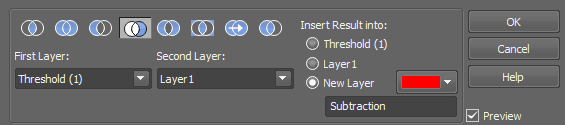
Figure 1845.
Choose one type of operation using the icons in the top row:
 AND
AND Intersection of the selected binary layers will be performed.
 OR
OR Union operation will be performed on the selected binary layers.
 Create Subtraction of the Second Layer from the First Layer
 Subtraction of the second layer from the first layer will be performed.
 Create Subtraction of the First Layer from the Second Layer
 Subtraction of the first layer from the second layer will be performed.
 XOR
XOR Non-Equivalence operation will be performed on the selected binary layers.
 EQ
EQ Equivalence operation will be performed on the selected binary layers.
 Copy the first layer
 First layer will be copied to a layer selected in the Insert Result into option.
Select which binary layers will be used in the operation.
Decide in what layer the result of the operation will be stored - either in one of the selected (source) layers or in a New Layer which will be created upon the binary operation start.
Select this option to preview the effect of the operation on the current image.
Procedure
Runs the Binary > Define Threshold command and saves the resulting binary layer as the graticule image.
Opens the binary editor in which it is possible to draw/edit the graticule mask.
See also Drawing tools
Displays a dialog window which selects a file with the graticule, previously exported via the Binary > Mask > Save Mask command.
Sets transparency of the graticule mask. The following options are available:
Only a single pixel contour around the mask is shown.
The mask is shown partially transparent.
The mask is shown in full color without any transparency.
Opens the graticule properties window and selects the Mask type. See Binary > Mask > Mask Properties. Mask will be activated after clicking the button.
Morphological opening performs Erosion followed by Dilation. This has the effect of clearing all objects which are too small with respect to the specified parameters. Larger structures are not significantly affected.
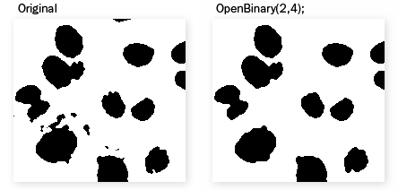
Figure 1846. Example
The Open on Binary Image dialog box appears.
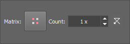
Figure 1847.
Click the button to change the structuring element used for this operation. See Structuring Element = Kernel = Matrix.
Number of iterations.
 Reset
Reset Sets the dialog default values.
Select this option to preview the effect of the operation on the current image.
See ND2 Files Processing for description of common settings.
Morphological closing performs Dilation followed by Erosion. It fills all holes in objects which are too small with respect to the specified parameters. Closely neighboring objects get connected.
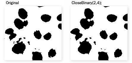
Figure 1848. Example
Figure 1849.
Click the button to change the structuring element used for this operation. See Structuring Element = Kernel = Matrix.
Number of iterations.
Reset Sets the dialog default values.
See ND2 Files Processing for description of common settings.
Erosion sets each pixel to the value computed as minimum from all pixels in the matrix. Erosion shrinks objects and removes small ones. A non-convex object can split into several parts.
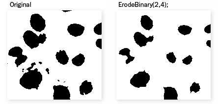
Figure 1850. Example
The Erode Binary Image dialog box appears.
Figure 1851.
Click the button to change the structuring element used for this operation. See Structuring Element = Kernel = Matrix.
Number of iterations.
Reset Sets the dialog default values.
Select this option to preview the effect of the operation on the current image.
See ND2 Files Processing for description of common settings.
See Also
Binary > Dilate
Dilation sets each pixel to the value computed as maximum from all pixels in the matrix. Dilation expands objects and structures in binary image. Neighboring objects are connected and small holes are filled.
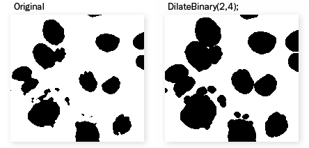
Figure 1852. Example
The Dilate Binary Image dialog box appears.
Figure 1853.
Click the button to change the structuring element used for this operation. See Structuring Element = Kernel = Matrix.
Number of iterations.
Reset Sets the dialog default values.
Select this option to preview the effect of the operation on the current image.
See ND2 Files Processing for description of common settings.
See also Binary > Erode. Removes small objects from binary image. This transformation is also called geodesic opening. First, the image is eroded and small objects disappear. Then the remaining eroded objects are reconstructed to their original size and shape. The advantage of this algorithm is that small objects disappear but the rest of the image is not affected. The function can be performed repeatedly.
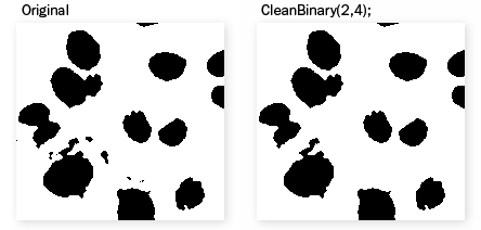
Figure 1854. Example
Figure 1855.
Click the button to change the structuring element used for this operation. See Structuring Element = Kernel = Matrix.
Number of iterations.
Reset Sets the dialog default values.
See ND2 Files Processing for description of common settings.
Removes small holes from the current binary image.
Fills all holes in the binary image which would be destroyed by Erosion of the specified parameters.
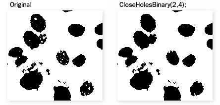
Figure 1856. Example
The Close Holes dialog box appears.
Figure 1857.
Click the button to change the structuring element used for this operation. See Structuring Element = Kernel = Matrix.
Number of iterations.
Reset Sets the dialog default values.
See ND2 Files Processing for description of common settings.
Smooths binary image contours.
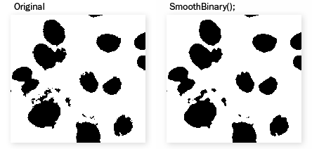
Figure 1858. Example
Figure 1859.
It is possible to define the strength of the function by specifying the number of iterations.
Reset Sets the dialog default values.
Apply the command to the whole image sequence, the selected dimension or just the current image frame. See ND2 Files Processing.
Select this option to preview the effect of the operation on the current image.

Fills in holes in binary image.
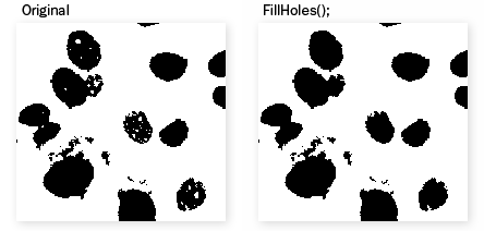
Figure 1860. Example
See ND2 Files Processing for description of common settings.
Expands non-convex binary image objects to their convex boundaries. Convex hull of an object can be defined as the intersection of all half spaces that contain the object, i.e. it is the smallest convex set, which covers the object. This operation uses half spaces rotating in 10 degrees step. Union of all convex hulls is displayed.
Figure 1861. Example
See ND2 Files Processing for description of common settings.
Transforms binary image to its 1 pixel wide contour.
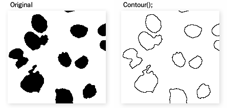
Figure 1862. Example
See ND2 Files Processing for description of common settings.
Converts binary objects to their centroids. Select the method of determining centroid positions.
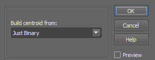
Figure 1863.
Only the shape of each binary object will be taken into account.
If bright/dark areas dominate aside of the centroid position calculated from just the binary layer, the centroid will be shifted in that direction.
See ND2 Files Processing for description of common settings.
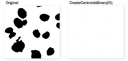
Figure 1864. Example

Separates binary objects into multiple smaller objects. The higher the Count, the fewer objects will be separated.
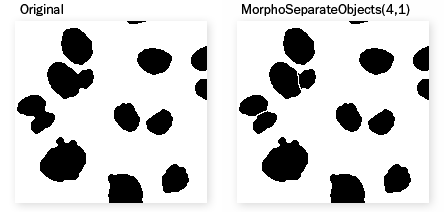
Figure 1865. Example
Morpho Separate Objects dialog box appears.
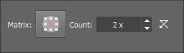
Figure 1866.
Click the button to change the structuring element used for this operation. See Structuring Element = Kernel = Matrix.
Number of iterations.
See ND2 Files Processing for description of common settings.
This command deletes every binary object which touches the image border.
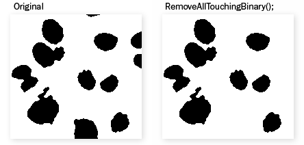
Figure 1867. Example
Performs morphologic opening on binary image using the selected linear matrix. The choice of the structuring element defines the direction in which the binary image will be affected. See Binary > Open.
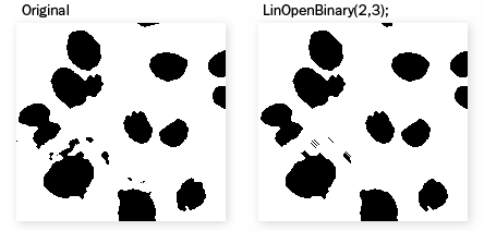
Figure 1868. Example
The Linear Open Binary Image dialog box appears.
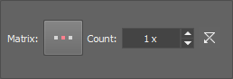
Figure 1869.
Click the button to change the structuring element used for this operation. See Structuring Element = Kernel = Matrix.
Number of iterations.
Reset Sets the dialog default values.
See ND2 Files Processing for description of common settings.
Performs morphologic closing on binary image using the selected linear matrix. The choice of the structuring element defines the direction in which the binary image will be affected. See Binary > Close.
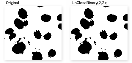
Figure 1870. Example
The Linear Close Binary Image dialog box appears.
Figure 1871.
Click the button to change the structuring element used for this operation. See Structuring Element = Kernel = Matrix.
Number of iterations.
Reset Sets the dialog default values.
See ND2 Files Processing for description of common settings.
Performs erosion on binary image, it removes a layer of pixels in the direction of the selected matrix. See Binary > Erode.

Figure 1872. Example
The Linear Erode Binary Image dialog box appears.
Figure 1873.
Click the button to change the structuring element used for this operation. See Structuring Element = Kernel = Matrix.
Number of iterations.
Reset Sets the dialog default values.
See ND2 Files Processing for description of common settings.
Performs dilation on binary image, it adds a layer of pixels in the direction of the selected matrix.
See also Binary > Dilate.
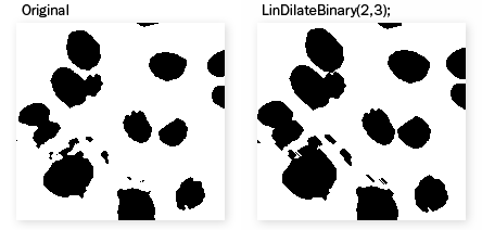
Figure 1874. Example
The Linear Dilate Binary Image dialog box appears.
Figure 1875.
Click the button to change the structuring element used for this operation. See Structuring Element = Kernel = Matrix.
Number of iterations.
Reset Sets the dialog default values.
See ND2 Files Processing for description of common settings.
See Also
Binary > Erode
Performs conditional dilation on binary image.
Note
The current binary image is dilated and then intersected by reference binary image. This step is repeated until there is no difference in the sequence of consecutive images. The current image may be e.g. erosion of the original image copied to reference binary image. In this case the function reconstructs only bigger objects and rejects smaller objects.
See ND2 Files Processing for description of common settings.
Creates zones of influence by drawing four connectivity borders. For each pixel of a border between two objects, the distance to both objects is the same.
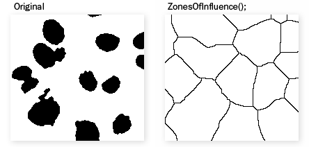
Figure 1876. Example
See ND2 Files Processing for description of common settings.
Marks objects with homotopic marks. Homotopic marking is a sequential homotopic thinning. It is used for marking objects. A filled object (with no holes) is transformed to a single point. Every hole leaves a closed contour.

Figure 1877. Example
See ND2 Files Processing for description of common settings.
Sequentially removes end-points from binary image. This function is used for simplification of skeletons by removal of branches. Closed contours remain unchanged.
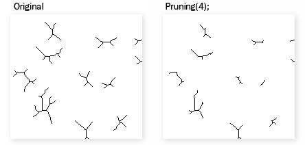
Figure 1878. Example
The following window appears.
Figure 1879.
Specifies the number of iterations; 0 stands for complete removal of branches. This command is mainly used for skeletonized images.
Select this option to preview the effect of the operation on the current image.
Apply the operation to the current image and close the window.
See ND2 Files Processing for description of common settings.
Extracts points from binary image according to structuring element. The Hit-Or-Miss Transformation dialog box appears.
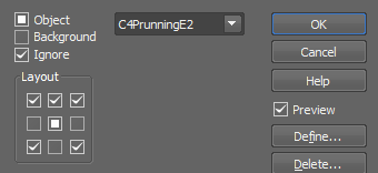
Figure 1880.
Identifies the state of each pixel in a structuring element.
An edit window where user defines the state of each pixel of a structuring element.
Displays relevant help page.
Select this option to preview the effect of the operation on the current image.
Opens a window for editing a user-defined structuring element.
Deletes the currently selected structuring element.
Apply the operation to the current image and close the window.
Note
The Hit-Or-Miss transformation maps binary image to the binary image in the following way: only points that match the structuring element retain in the binary image. Matrix elements values are 0, 1 or 2. 0 specifies the background, 1 specifies the foreground (objects) and 2 specifies that this position in the Matrix can be ignored (either foreground or background). E.g. when selecting Hit-Or-Miss transformation with SinglePoint structuring element, only isolated single points remain in the binary image.
See ND2 Files Processing for description of common settings.
Dilates a binary image without changing the number of objects - it is a homotopical transformation.
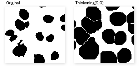
Figure 1881. Example
When you invoke this command, the Thickening dialog box appears.
Figure 1882.
Specifies the number of iterations, i.e. number of layers being added to each object. Parameter 0 performs ultimate dilation (neighboring objects touch each other).
If checked, conditional thickening is performed. Objects in the current binary image are thickened and then intersected with the reference binary image.
Select this option to preview the effect of the operation on the current image.
Apply the operation to the current image and close the window.
Displays the relevant help page.
See ND2 Files Processing for description of common settings.
Displays the distance of each object pixel to the nearest boundary (background pixel) as an intensity value.
The resulting color image is a 16-bit image (to cover distances longer than 255 px)
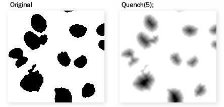
Figure 1883. Example
The Distance function dialog box appears.
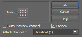
Figure 1884.
Click the button to change the structuring element used for this operation. See Structuring Element = Kernel = Matrix.
A new channel will be created containing the result of the function (otherwise the current image is converted to a mono image).
Select a binary layer to which the resulting channel will be attached. A virtual link is created, the attached binary layer inherits color of the channel and its visibility is synchronized with the channel. See also View > Analysis Controls > Binary Layers .
Apply the operation to the current image and close the window.
Select this option to preview the effect of the operation on the current image.
See ND2 Files Processing for description of common settings.
Sequentially erodes binary image, but leaves small areas which would completely disappear in the next erosion.
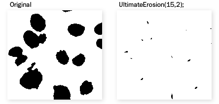
Figure 1885. Example
The Ultimate Erosion dialog box appears.
Figure 1886.
Click the button to change the structuring element used for this operation. See Structuring Element = Kernel = Matrix.
Set 1 for maximum possible erosion. Any number higher than 1 will do fewer erosions and preserve bigger parts of each object.
Apply the operation to the current image and close the window.
Select this option to preview the effect of the operation on the current image.
See ND2 Files Processing for description of common settings.
This command creates the granulometry image from the binary image.
Creates zones of influence by the fast 'pipe of pixels' algorithm. Performing this command, the ZonesOfInfluenceFast is called and appended to the list of executed functions.
This command creates medial axis from the current binary objects.
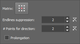
Figure 1887.
Specifies a structuring element for finding the distance to the boundary.
Determines the axis shape. The higher is the value, the more simple is the shape.
Determines how many points are used to calculate the direction of the medial axis prolongation. Values are larger than 2.
Determines whether the medial axis prolongation is used or not.
Select this option to preview the effect of the operation on the current image.
See ND2 Files Processing for description of common settings.
This operation adds pixels to ensure that each pixel which is only 8-connected will become 4-connected. 4-connected pixels are those connected vertically or horizontally, but not diagonally.
See Connectivity.
See ND2 Files Processing for description of common settings.
This operation removes pixels to ensure that each pixel which is only 4-connected will become 8-connected. 8-connected pixels are those either vertically, horizontally, or diagonally. See Connectivity.
See ND2 Files Processing for description of common settings.
Connects binary objects which are closer to each other than the specified distance by a thin line.
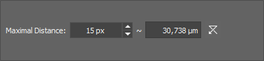
Figure 1888.
Set the maximal distance of two objects to be connected.
See Image processing for description of other settings.
Makes a skeleton of the binary image. The current binary image is dilated and then intersected by reference binary image. This step is repeated until there is no difference in the sequence of consecutive images. The current image may be e.g. erosion of the original image copied to reference binary image. In this case the function reconstructs only bigger objects and rejects smaller objects.
Skeleton is a representation that largely preserves extent and connectivity of original binary objects, while pruning most of original pixels.

Figure 1889. Example
See ND2 Files Processing for description of common settings.
The purpose of this command is to create 1pixel seeds out of a skeletonized binary image. This function serves for automatic recognition of the intersection points of single-pixel lines.
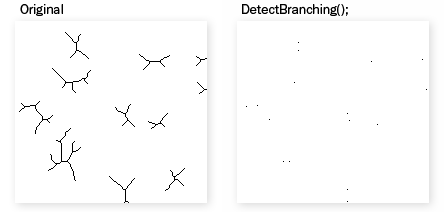
Figure 1890. Example
Purpose of this command is to create 1pixel seeds out of a skeletonized binary image. It preserves only ending points of the skeleton and clears all other pixels.
On a skeletonized binary image, branches (free endings) shorter than the defined length will be removed.
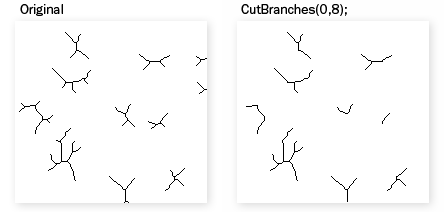
Figure 1891. Example
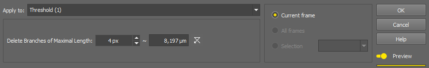
Figure 1892.
Shorter branches will be deleted.
Note
“Recursively” means that the function is called repetitively until there are some branches left to be cut.
On a skeletonized image, connects branch peaks. Set sensitivity of the function in the window:
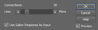
Figure 1893.
Set sensitivity of the function. The higher the more connections will be created.
Apply Gabor edge detection to the image before evaluating the edge strength.
On a skeletonized image, circular (enclosed) objects with equivalent diameter (eqdia) smaller than the defined value will be deleted. You do not necessarily want to delete small objects but the ones which are mis-detected.
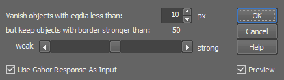
Figure 1894.
Objects with eqdia smaller than this value will be erased.
Set the threshold value for deletion. Binary objects containing a strong-enough edge in the color image will be preserved regardless of the eqdia value.
Apply Gabor edge detection to the image before evaluating the edge strength.
This command applies maximum intensity projection to all binary layers of the current T or Z ND2 image (The T or Z dimension is required). The result will be union of the binary layers.
This command applies minimum intensity projection to all binary layers of the current T or Z ND2 image. The T or Z dimension is required. The result will be intersection of the binary layers.
This command can be used for interactive calling of NIS-Elements drawing functions. The Insert dialog box appears.
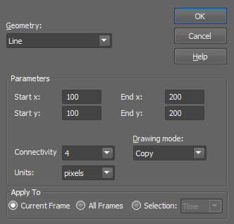
Figure 1895.
Select the type of geometry you wish to draw (i.e. one of the following):
Calls the InsertLine function which inserts a line in the image.
Calls the InsertLines function which inserts two parallel lines in the image.
Calls the InsertCircle function which inserts a circle in the image.
Calls the InsertEllipse function which inserts an ellipse in the image.
Calls the InsertRectangle function which inserts a rectangle in the image.
Calls the InsertMarkers function which inserts a grid of markers in the image.
Calls the InsertMarker function which inserts one marker.
Number and type of parameters changes accordingly to the selected geometry.
4 or 8, defines the way a line is drawn. See Connectivity.
The distance between parallel lines. Selected Units are used to specify the coordinates.
You can select a logical operation which will be performed between the existing binary layer and the object(s) being inserted.
Closed shapes can be either filled or hollow. Select TRUE to fill the shape or FALSE to leave it hollow.
Depending on the selected geometry, these parameters define distances significant for each shape. Selected Units are used to specify the distances.
When inserting markers, one of the predefined marker shapes can be selected from a pull-down menu.
These parameters specify orientation of the object in degrees [°].
Depending on the selected geometry, these parameters define coordinates significant for placement of the shape (center for a circle, start/end for a line, etc...). Selected Units are used to specify the coordinates.
Select whether the coordinates/dimensions of the shape will be specified in pixels or in the image calibration units.
Note
This option appears only if the current image is calibrated.
Apply the operation to the current image and close the window.
See ND2 Files Processing for description of common settings.
(requires: Advanced 2D Tracking)
This command tracks binary objects. See Tracking for more information.
Inverts the binary image to its negative.
See ND2 Files Processing for description of common settings.