Undo History

Copy Selection
Paste
Region

Invoke the command and the cursor changes.
Draw the circle inside the image and release the mouse button.
Everything inside the selected area will be replaced by a background color according to the Edit > Region > Region Settings.
Invoke the command, the cursor shape changes.
Click on the object of which edges should be detected.
The detected area is indicated by a color line. The area size can be modified by operating mouse wheel or arrow keys up and down.
When you are satisfied with the result, confirm the cut by a secondary mouse button click or Enter.
Invoke the command, the cursor shape changes.
Click to define the center and drag the mouse holding the button down to set the diameter.
When the mouse button is released, the indicated area is copied to memory.
Invoke the command, the cursor shape changes.
Click on the object of which edges should be detected.
The detected area is indicated by a color line. The area size can be modified by operating mouse wheel or arrow keys up and down.
When you are satisfied with the result, confirm the copy by a right mouse click or Enter.
Select the orientation, scale type, line color, line width, scale size (in pixels), the background color, the text visibility and the scaling method.
Click the Burn button
Click and hold down the primary mouse button to adjust the scale position (the scale is displayed and you can drag it within the image).
Release the mouse button.
Call the Edit > Create New Document from Current View command. A new image is created.
Or, right click the top or one of the side projections within the Slices View , and select the Create New Image command from the context menu. The new image will contain image of the selected projection.
Call the Edit > Create New Document from Current View command. A new image is created.
If the original ND2 file contains N dimensions, one dimension will be used to create the MIP images, and therefore the new image will be composed of (N-1) dimensions.
Use the Applications > EDF commands to create the EDF Focused View.
Call the Edit > Create New Document from Current View command. A new image is created.
Histogram
Intensity Profile
Time Measurement
ROI Statistics
Spectrum Profile
Colocalization
XYZ Overview
Tracking
Polar Graph
Kymograph
Note
The Kymograph option is enabled only if a linear annotation object is present in the image.
Clicking the up/down arrow by the edit box switches between the 8 pre-defined positions.
Clicking inside the preview rectangle (with the arrow) turns the arrow tip to one of the 8 pre-defined positions.
An arbitrary value (e.g. 113°) may be written inside the edit box.

Displays current image as it looked like before the most recent transformation.
Note
When using this command twice subsequently the transformed image is displayed again. This command may be used several times for comparing the original image with the transformed one.

This command is designed for comparing images before and after the last performed adjustment. If you call this command twice, it behaves like invoking Undo , followed by Redo, so you see the newest image of the command history.
Calling this command, all undo history items except the current one and the original will be taken back.
There is a list of performed image operation in the submenu. Selecting one, you roll back through the command history to the image version after the operation selected. Calling this command, all newer versions than the one you are returning to will be discarded.
This command restores original appearance of the image (as it was acquired or opened) but keeps the other layers (binaries, ROIs, ...) intact.

Copies the content of the current image window to the clipboard. The current image can contain several layers (e.g. binary layer, interactive length measurement results...). All these additional elements are copied along with the color image. The actual zoom settings do not affect the clipboard content, it is always the entire image copied.
Allows you to select a rectangle within the picture window and then copies it to clipboard. The cross-style cursor appears.
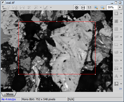
Figure 1681.
First, a copy-rectangle cursor appears. You should select a rectangle you want to copy: position the cursor to the upper-left corner and then press and hold down the primary mouse button while moving the cursor to the bottom-right corner of the rectangle. Then, release the mouse button. If you are in Overlay mode, it copies the binary image too. Confirm the selection with right click or by pressing Enter.
Allows you to select the most recently used rectangle selection within the picture window and then copies it to clipboard. A copy-rectangle cursor appears with dimensions of the most recently used rectangle. Adjust the rectangle dimensions and position when needed and confirm the selection by one secondary mouse button click or by pressing Enter.

This command creates a new image, and inserts the clipboard content into it. The new image is called 'New Image 1, 2, ...'.
This command takes clipboard content and appends it to the current image as a new channel/channels. The behaviour of this command depends on the type of images used:
The original RGB image is converted to one Brightfield channel and the other channel(s) are appended, a multichannel image is created.
If an RGB image is in the clipboard and you paste it as new channel(s), it is converted to one Brightfield channel and appended to the others. A multichannel image is created.
When pasting one or more channels to mono or multichannel image, the channels are simply appended. A multichannel image is created.
This command takes clipboard content and appends it to the current image as the Brightfield channel. The bright field channel can contain monochromatic or RGB images.
This command pastes clipboard content into a selected channel. The original channel contents is replaced by the pasted.
Enables positioning of the upper-left corner followed by pasting from clipboard. The paste-origin cursor appears. You can not modify the rectangle selection. Confirm the position with the secondary mouse button.
Enables positioning and resizing of a rectangle that keeps the aspect of an image to be pasted from clipboard. After positioning and resizing, press the secondary mouse button to paste the image.
Enables rectangle selection of current image followed by pasting from clipboard. If the selection area does not match the clipboard image dimensions, the image will be stretched to fit the selection. You are able to modify the rectangle selection.
Performs a freehand cut operation on the current image. To finish region definition, press the secondary mouse button. The region will be cut out.
This command cuts out a circle shaped area from the current image.
This command enables you to cut an automatically detected area and store it to clipboard.
Performs a freehand copy operation on the current color image. To finish region definition, press the secondary mouse button. The region will be copied to clipboard.
This command enables you to copy a circle-shaped area to clipboard.
This command enables you to copy an automatically detected area to clipboard.
Pastes the previously copied region to the image. You can freely change the image position and rotation.
Allows to modify the current cut fill color and enables the user to draw a freehand region from the current image.
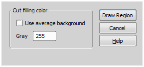
Figure 1682.
After you press the Draw Region button, mouse cursor changes. Draw a region boundary and confirm it with the mouse right-click. To draw multiple regions, press and hold Ctrl and draw regions. To close them use the mouse right-click. Release Ctrl before closing the last region to finish the drawing.
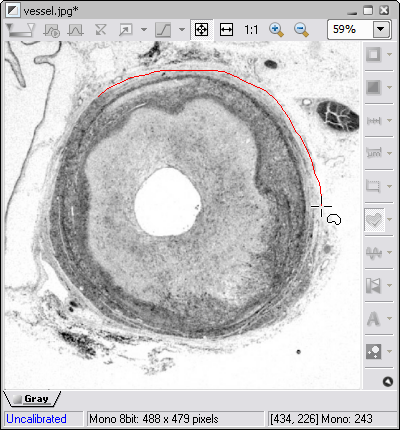
Figure 1683.
The image outside the selected region is deleted and filled with color specified by the Edit > Region > Region Settings command.
This command opens the Region Settings dialog window enabling to set the color filling the background of the binary layer. A specific color value can be entered into the edit box - Red, Green and Blue (for RGB images) or Gray values (for gray images). Average color (average value calculated from the background pixels) can also be used to fill the binary background (Use average background).
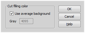
Figure 1684.
Allows to modify the current cut fill color and the mode of the paste operation (normal / smooth). The rest of data that wasn't selected by the Edit > Region > Accepted Region command and so are outside the defined border are deleted and filled with the cut filling color.
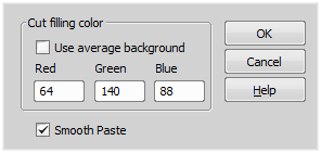
Figure 1685.
You can either use the neutral predefined background color, or define your own background color. Fill in the Red, Green, and Blue (for RGB images), or Gray values of the desired color. If one or more values exceeds the value range (255 in 8bit pictures), it is automatically reset to the highest value (255) after the button is pressed.
The Smooth paste option smooths the borders of the pasted regions.
Replaces current color image with an overlay image. This command can be used if you want to insert measurement annotations or binary layer into the current color image.
Note
After performing this command, NIS-Elements automatically switches to the color image view.
This command inserts scale into the current color image so that the scale becomes part of it. A dialog box appears.
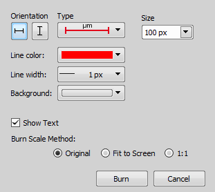
Figure 1686.
Burn Scale Method
This option determines how the inserted scale will be resized - it can prevent inserting a too small or too large scale.
Burns the scale in the size as you see it in the image in the current zoom.
Burns the scale as if you zoomed the image to the Fit to Screen mode and applied the Original method
Burns the scale as if you zoomed the image to 100% and applied the Original method.
Inserts a spectral scale bar into the current spectral image so that it becomes part of the image. Click on the center of the spectral bar to move it around or click on its edges and drag to adjust the scale size.
This command changes dimensions of an opened image.
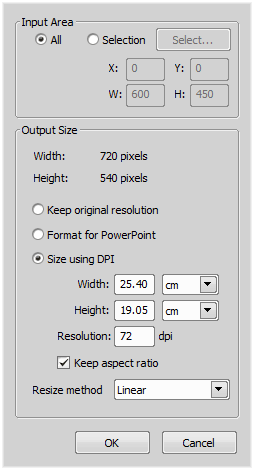
Figure 1687.
Dialog Box Options
Define what is exported - for the whole image select the option All, or define a Selection from the image. When you press the Select button, a red rectangle appears in the image. Adjust its dimensions and position to fit the part of the image you want to export. Confirm selection with a secondary mouse button.
Width and height of the exported image is displayed and recalculated automatically whenever you change some parameter.
Keeps original resolution of the image.
Scales down the image to fit dimensions used in PowerPoint presentations.
Changes dimensions and resolution of the exported image. Default values are prefilled. If you enter a different value, distortions of the image may occur. Check the Keep aspect ratio option to keep the set aspect ratio while resizing.
Choose which method is used to resize the image: Quick, Linear, or Splines. These methods differ in precision of the result and in speed of processing.
This command creates a new color image of “what you see”. A new image window is opened and the new image is called “View Snapshot”.
The snapshot includes even the magnifier glass tool when the X shortcut is used:
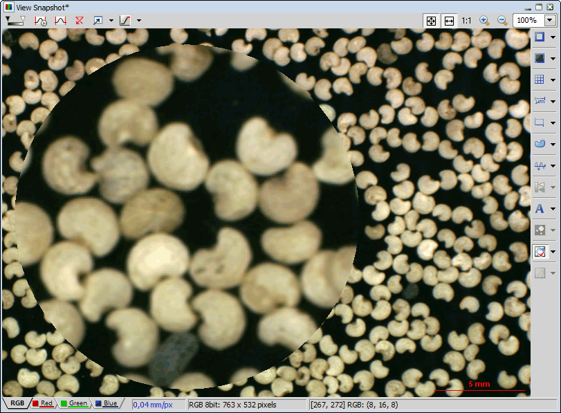
Figure 1688.
When you are working with ND2 files, select the frames to which the function is applied in the window that appears.
A snapshot of a rectangular area can be created by this command.
Figure 1689.
Selecting the command invokes the Crop cursor. Frame the area you want to include in the snapshot with a red rectangle. Use the white squares on the rectangle edges to adjust its size, and drag it with the primary mouse button to set its position. Finish the command with the right click or by pressing Enter. A new image called View Snapshot will be created. All objects will be merged down to one color image.
Figure 1690.
Cropping Molecule Images
(requires: N-STORM Analysis)
If cropping molecule images (see N-STORM), selecting this command invokes the Crop cursor. Frame the area you want to include in the snapshot with a red rectangle. Confirm on which dimensions the crop will be applied (Apply to) and click . Now you can adjust the crop using the white squares on the rectangle edges and drag it with the primary mouse button to set its position. You can also use the opened dialog window to set the source/destination size and position together with the Height percentage (zoom level of the snapshot). The higher the zoom, the more details are rendered. Confirm the settings by clicking . A new image called View Snapshot will be created. All objects will be merged down to one color image.
This command creates a snapshot of the whole image, no matter if its fully visible or not. However the image is zoomed in, it creates a new image with the current (zoomed) image resolution. Had you an image 250x250 pixels zoomed to 300%, the Create Full View Snapshot command creates a new image of the size 750x750 pixels.
(requires: N-STORM Analysis)
Opens the Create raster document from molecules dialog used for creating a custom raster from the currently opened molecule image. For more information please see Create raster document from molecules.
This tool can be used to make screenshots within NIS-Elements. After execution a red rectangular is displayed, dynamically changing with the mouse cursor position. Select the desired area for the capture and click the primary mouse button to copy the selection to clipboard. Then you can paste it into a new document.
Tip
Use the Ctrl + Enter keyboard shortcut.
This command displays the sequence of images as a 3D model using perspective projection. Please see Volume Viewer.
This command creates a new image from the current ND / EDF Focused view. It maintains resolution and channel structure of the original image (unlike the Create View Snapshot commands). The command is applicable to the following views:
This command creates an image montage. The montage can contain: opened image, another currently opened images, and different control panel screen shots. The following window appears:
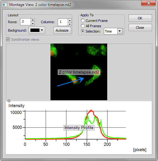
Figure 1691.
Define the layout appearance by setting the number of rows and columns. The layout is divided into cells. Position of the border between the cells can be adjusted by dragging the border line. To join/split two adjacent cells, click on the white square. Each cell can contain image data of one of the opened images (Images) or a snapshot of a control window or control panel (Controls). Choose the cell content by pressing in the middle of an empty cell and select the content from the contextual menu:
Shows a list of currently opened images.
Shows a list of control panels which can be inserted in the cell. The displayed data are loaded from the currently active image window.
Borders can be specified for each cell. Click this command and define top, left, right, and bottom border width. Units are percentage of the cell size.
You can edit the cell size by moving the lines - press the white square button placed on the border cell to merge or separate adjacent cells. After you press the OK button, the dialog is closed and a montage image is created.
Other Options
Enter number of rows, columns and choose color of the canvas background. Press the Autosize button and the system automatically sets size of cells so they correspond to their content.
See ND2 Files Processing.
Pastes text into the current color image. The Insert Text dialog box appears:
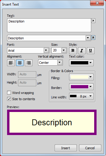
Figure 1692.
Type the text you want to insert.
Type or select a font name. NIS-Elements lists all available fonts compatible with the current printer driver and additional fonts installed in your system.
Type or select a size. The available font sizes depend on the printer and the selected font. If the size you type is not available on the current printer, NIS-Elements chooses the closest available size.
Select the font style (bold, italic, underlined).
Aligns the text within the text frame to left, right, or center.
Aligns the text within the text frame to top, bottom, or center.
Select one of the 16 predefined colors or define your own.
Dimensions of the text frame can be inserted.
A word wrap will be applied to the text.
The measurement frame will fit to its contents. The Width and Height fields become disabled.
Define the background color, border color and border line width.
Shows the effects of the formatting you specify before pasting it to the image.
Inserts an arrow into the current annotation layer of the image. The Insert Arrow dialog box appears.
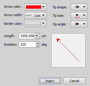
Figure 1693.
Select appropriate color contrasting with the background.
Select the arrow width (1-8 pixels).
Select the arrow border color.
You can adjust the arrow tip size selecting from the predefined shapes.
Define the arrow length in pixels.
NIS-Elements offers 8 pre-defined arrow orientation - 0°, 45°, 90°, 135°, 180°, 225°, 270°, 315°. There are three ways to define the arrow orientation:
This item influences the inserted arrow. The angle of rotation will be counted for the arrow tip.

When you double click the caption of the main NIS-Elements window or run the Edit > Options command, a window with options for the software appears. For description, please see General.