Import/Export

Open/Save Next
Report
New Report from Template
Select the destination directory where the files will be stored.
Define the prefix to determine the resulting file names. A number will be appended to this prefix.
Select the Split button.
The window closes and the files will be created in the destination directory (they will not open automatically).
Select the dimension types from the combo boxes to define the dimensions order.
Define the number of loops for each dimension in the Statistics portion of the window.
Set the filtering conditions through the Advanced File Filter dialog.
Select one file of the files in the list to determine the image sequence (images with the same prefix are automatically selected).
Specify the Dimensions properties in the right portion of the window.
Confirm the options by the Convert button.
Browse for the image sequence within the Directories portion of the window.
All images of the selected directory appear in the list of files in the middle of the window.
There might be several sequences in the directory. Just click on one file of the desired sequence and it will be detected automatically (under condition of having different prefixes). Other files will look disabled (gray).
When a sequence is selected, the filenames are automatically searched for the indexes, and the indexes are marked with color according to dimension types selected in the above pull-down menus.
Change the dimension order by selecting from the pull-down menus, if needed.
Check, whether the system recognized the right image order, and define the properties of selected dimensions in the rightmost portion of the window.
Click Convert to start the ND2 file creation. The file will be placed as defined in the Output File Name field.
Select the dimension types from the combo boxes to define the dimensions order.
Define the number of loops for each dimension in the Statistics portion of the window.
Set the filtering conditions through the Advanced File Filter dialog.
Select one file of the files in the list to determine the image sequence (images with the same prefix are automatically selected).
Specify the Dimensions properties in the right portion of the window.
Confirm the options by the Convert button.
Define the File Folder where the images will be saved.
Select between the Tagged Image Format and JPEG2000 file formats.
Fill in the file name prefix after which the indexes of dimensions will be placed.
Select the method the channels will be treated with (see below) in the Channels section.
Select the Index order. (Lets say you have two dimensional ND2 file with “t” and “z”. If a “t,z” order was selected, the image frames would be ordered “t1z1, t1z2, t2z1, ...”, otherwise, the order would be “z1t1, z1t2, z2t1,...”
Press the Export button.
Click the Export to ASCII command and the cursor changes.
Select an area and adjust the size of the red rectangle. Confirm the export with right click.
The following dialog box appears:
Names of all image files currently opened in the software will appear on the right side.
Select those you do not want to merge and use the button to remove them from the list on the right.
Use the arrow buttons to adjust order of the files (see Merging Rules below).
Click .
Click the button and browse for the folder where your images are saved.
Choose whether to include images placed in Subfolders in the list.
Select images to be merged in the left column and use the button to add them to the list on the right.
Use the arrow buttons to adjust order of the files (see Merging Rules below).
Click .
Click .
The Load Image Sequence dialog appears:
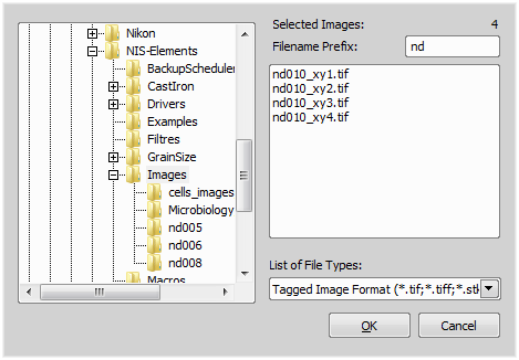
Figure 1668.
Browse for the directory where the sequence is saved.
Select the files to be loaded by defining the File Names restriction. (e.g. “Large” will restrict the selection only to files beginning with the word “Large”).
Click . The dialog closes and the selected files are loaded to the main window.
The preview of loaded images is arranged inside the window according to the Columns/Rows value - depends on your choice of the Vertical/Horizontal direction. Change it to change the arrangement.
Select whether the images were captured in meander or rows direction and set the position of the First frame.
Choose the Overlap rate from the combo box. Select the best value according to the preview image.
 Auto scale automatically sets LUTs for better visualization.
If you check the Image Registration option, the images will be merged using a special algorithm which tries to fit and smooth the edges.
The Crop a border option crops the large image so that no background (caused by the image registration algorithm) will be included in the result. When image registration is used and the result is not cropped, it contains asymmetric black borders.
Stitching option is used to select a stitching method (see: Methods Used for Stitching Large Images). Blending method blends the overlapping image parts and Optimal path method computes a contour in places where two overlapping images are least different and then they are stitched copying this contour.
Shading correction function is appropriate for sufficient stitching of homogeneous images. Check Automatic shading correction to turn the function on and choose the type of correction which best represents the background of your sample image. If Automatically per channel is selected, the shading modality method is detected and applied per channel. For more information about shading correction, please see: Acquire > Shading Correction Panel.
When done with setting all of the options, click . When the stitching process finishes, the large image is opened as a new image called “Large Image #”.
Click this button.
A dialog box appears where the new Z-step can be set:
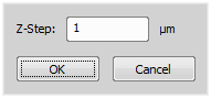
Figure 1674.
Set the step size and confirm it by OK.
Click the Edit T-Step button.
A dialog box appears where the new time interval can be set.
Set the interval length and confirm it by OK.

Creates a plain single colored image. The dialog values (width, height, colors, depth, etc.) are automatically pre-filled according to properties of the current, or the most recent image.
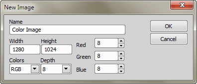
Figure 1648. Colors: RGB
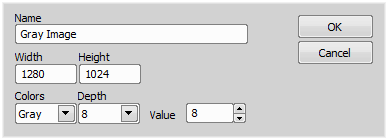
Figure 1649. Colors: Gray
The filename text will be used as a image name.
Width and height of the new image in pixels.
Intensity of all pixels in the new image. For an RGB image, define intensities of Red, Green and Blue channel. If you create a gray image, define its intensity (Value). The intensity range depends on the selected Depth: 0-255 (8bit), 0-1023 (10bit), 0-4095(12bit), or 0-65535(16bit).
Choose between an RGB image and a Gray image.
Bit depth (per channel) of the new image can be selected. Select 8, 10, 12 or 16.

With this command, you can load one or more images to the application. A dialog box appears. Multiple files selection can be performed holding the Ctrl or the Shift key.
The last-used directory is displayed. Roll the combo box down to browse network neighborhood, network or local drives, etc.
Some types of image files (bmp, jpg...) do not contain the calibration information. If the option Use current calibration is checked, such image isn't marked as uncalibrated after opening, but the current system calibration will be assigned to it.
 Information
 Image properties of the selected file can be displayed by pressing this button.
Type in this edit box and you will be offered files which match the already-typed characters.
Select an image format or All Images. Only files of the selected format will be displayed in the selection window.
Size of the selected image in pixels
Number of channels and their bit depth.
Number of dimensions (displayed for ND files only).
Size of the file on disk.
Note
Time Step Definition: Some ND2 files do not have the time step defined properly. When you open such ND2 file, a window appears, where the proper time step between the frames shall be defined.

Saves an image to a disk. In case of a new image that hasn't been saved yet, the File > Save As dialog box appears. Otherwise, the current version of the existing file is updated.
Saves the existing image under a different name. The following dialog box appears also when you invoke the command on a newly created image.
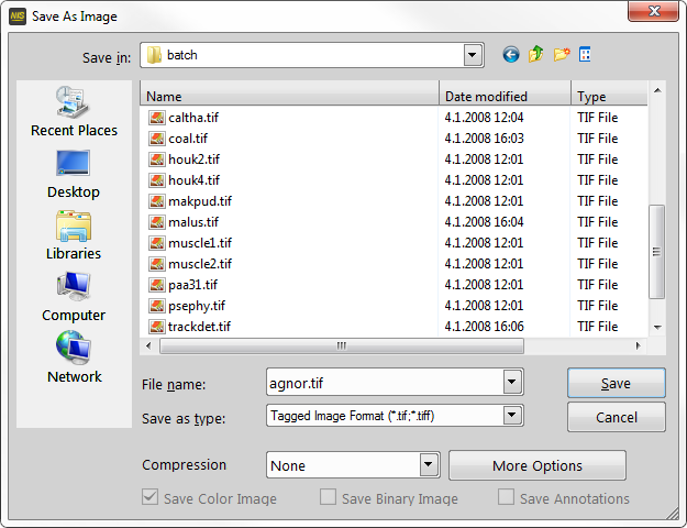
Figure 1650.
Name of the image being saved.
Specifies the file type, in which the image will be saved.
See also TIF Saving Options, AVI/MP4 Saving Options, Supported File Formats.
When pushing , the Archive information dialog box appears (For LIM and JPEG2000 formats only). Confirm it to save the image.
Closes the Save As Image dialog window without saving the image.
Choose the image compression ratio. Available compression modes depend on the selected Save as type.
Reveals more saving options.
Check this option to save the color image into the file.
Check this option to save the binary layer into the file. If the selected file format does not support layers, the option turns in Burn Binary Image. The binary data are burned into the color data before saving the file.
Check this option to save the annotation layer and the scale layer into the file. If the selected file format does not support layers, the option turns in Burn Annotations. The currently displayed annotation/scale data are burned into the color image before saving the file.
Sets the Windows Read-only attribute to the file being saved.
TIF Saving Options
If checked, channel combination of the source image is preserved.
Original bit depth of the new file can be maintained, or the file can be rescaled to 8- or 16-bits.
LUTs of the source image can be ignored (None), automatic LUTs can be applied (Apply auto LUTs) or LUTs saved with the image can be applied (Apply saved LUTs).
Color channel data can be saved per pixel to improve the TIFF file compatibility.
Each channel will be used to create a monochrome image.
Each channel will be used to create an RGB image in channel color or in grayscale.
Inserts scale into the final image. The scale becomes part of the image and cannot be removed.
Inserts the binary data into the final image. The binary data become part of the image and cannot be removed.
Inserts annotations into the final image. The annotations become part of the image and cannot be removed.
One RGB image is created from all channels available in the source image.
Note
Bit depth conversion cannot be used with spectral images.
OME metadata can be saved with the TIFF file to increase the TIFF file compatibility (e.g. proper channel designation).
See also Supported File Formats.
AVI/MP4 Saving Options
AVI and MP4 movie files can be created from a ND2 file. When the *.AVI or *.MP4 format is selected in the Save as type combo box, the following options appear:
Select which video compression is applied on created movie files. See About Video Compression.
When the ND document contains XY points, you can decide how this dimension is saved. Either only the current point can be saved into the file, or all XY points can be saved to separate files which are recognizable by the "_number" suffix.
Timing of frames of the resulting movie may equal the Original Acquisition Time. If this does not suit your needs, define a custom interval in ms.
Select the dimension, frames of which will be used to create the movie. The dimension must be present in the ND2 file necessarily.
The T dimension frames of the current Z stack position will be used.
The Z dimension frames of the current Time position will be used.
All frames of the ND2 file will be used in the movie.
When the Multipoint (XY) dimension is present, only frames of the current position are used automatically.
Opens the Export Images to TIFF dialog window enabling to export image files into TIFF format and to define its target parameters.
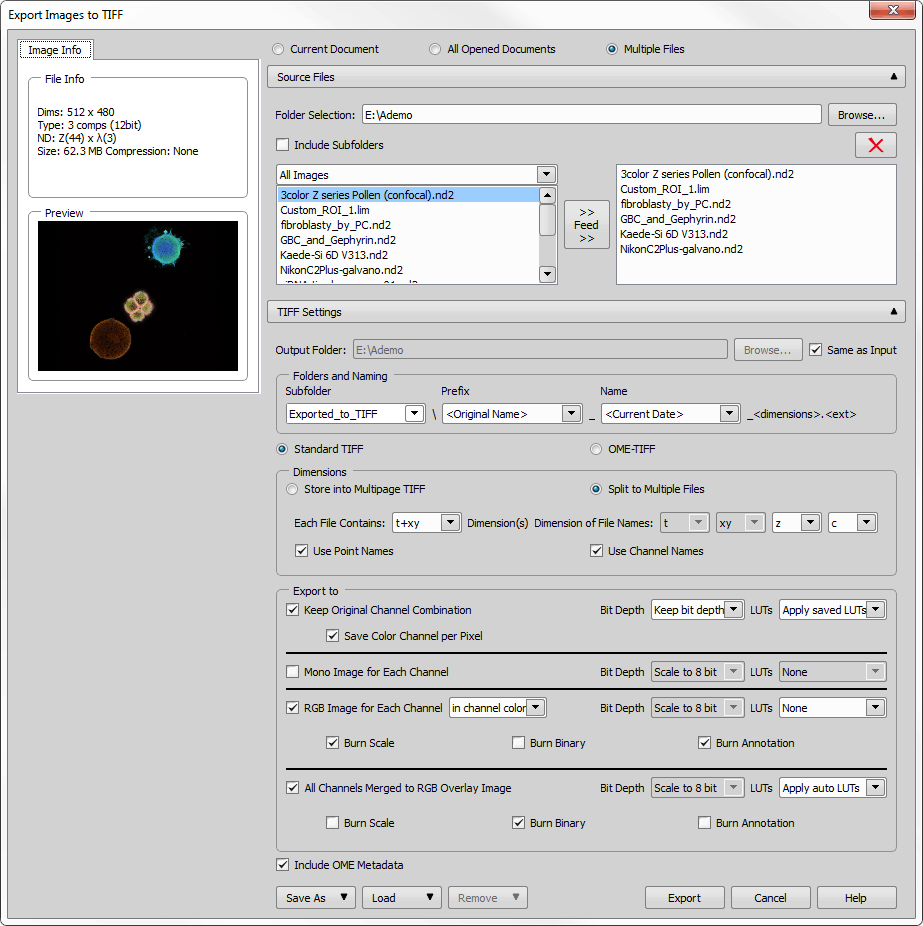
Figure 1651.
Dialog Window Options
Displays basic information about the currently selected image file together with its preview.
Determines which images will be exported to TIFF.
Displays/hides additional options when exporting Multiple Files.
Target folder for the exported TIFF files.
Even images in the subfolders are listed in the window below.
Moves the selected images from the left file list to the right. Only images in the right list will be exported to TIFF. To remove an image from this list, click  .
.
Displays/hides additional TIFF settings.
Defines where the TIFF files will be saved. Same as Input can be checked to save the files into their source folder.
These combo boxes define subfolder and file naming of the newly created TIFF files.
Switches between different TIFF formats.
A multi-page TIFF file will be created containing its dimensions in one file.
Dimensions are dismembered to create multiple TIFF files.
Defines the basic dimension(s) of the multi-page TIFF file.
Order of the dimensions used for file naming.
Names of XY multipoints present in the image will be used.
Names of the channels present in the image will be used.
If checked, channel combination of the source image is preserved.
Original bit depth of the new file can be maintained, or the file can be rescaled to 8- or 16-bits.
LUTs of the source image can be ignored (None), automatic LUTs can be applied (Apply auto LUTs) or LUTs saved with the image can be applied (Apply saved LUTs).
Color channels can be saved per pixel to improve the TIFF file compatibility.
Each channel will be used to create a monochrome image.
Each channel will be used to create an RGB image in channel color or in grayscale.
Inserts scale into the final image. The scale becomes part of the image and cannot be removed.
Inserts the binary data into the final image. The binary data become part of the image and cannot be removed.
Inserts annotations into the final image. The annotations become part of the image and cannot be removed.
One RGB image is created from all channels available in the source image.
Note
Bit depth conversion cannot be used with spectral images.
OME metadata can be saved with the TIFF file to increase the TIFF file compatibility (e.g. proper channel designation).
Saves the dialog window settings into the database (New...) or .xml file (Save to XML file...).
Loads the dialog window settings from the database or .xml file (Load from XML file...).
Removes the selected dialog settings from the database.
Starts the TIFF exporting process.
Closes the dialog window without applying any settings.
Opens this help page.

(requires: DBASE (Database))
Saves current image to database. This command displays the following dialog box:
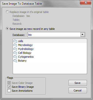
Figure 1652.
This option becomes active when you use the Save To Database command on the same image for the second time. If you want to replace the first copy with this second one, select it.
Choose the table to save the image to.
Check the image layers you wish to save within one database record. Enables you to save the binary or the color layer as a stand-alone image. The color image is saved every time.
When you press , the Database Record Fields window appears to be filled. Fill it in and press . If you use the command repeatedly, the button can fill the most recently used values inside the Database Record Fields window.
Closes the current image. If the image has been changed or is new, the user will be given a chance to save it.
See Closing Images.
This command reloads the last saved version of the current image from hard disk. If the image has been changed since the last save, a confirmation dialog appears.
This command creates a copy of the current image. Note, that the copy is created in a memory only and should be saved if you want to keep it.
Converts files to different image formats. The Convert Files dialog box appears:
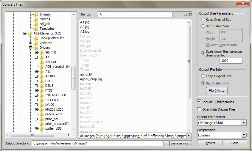
Figure 1653.
Specifies image file directory.
Lists all images of the selected type in the currently selected Directory.
This box allows you to narrow the selection of the files to convert. The Source box lists files that have the filename extension selected in the extension box below. To select a list of files that begin with particular letters, type the letters here.
Specifies filters for image files in the selected Directory.
Destination directory path. Press the Same as Input button to set quickly the same directory. If you want to choose a different output location, press the ... button and pick up another directory.
Maintains image's width and height.
Changes image's width and height to specified values.
If checked, height of the image is automatically recalculated to preserve aspect ratio.
Scales down the image. The longer side of the image is rescaled to the defined number of pixels while the aspect ratio is kept. Shorter side of the image is calculated automatically.
This option is available only for the JPEG2000 and the LIM format. You can keep original info or you can set a new one.
Keeps the original file info setting.
Allows to set custom image fields values. To set the new info, press the File Info button.
If checked, images in all subdirectories of the specified directory will be converted too.
Check this item to overwrite the original images with the converted ones.
Specifies destination image file format.
Specifies type of compression of the destination image.
Starts the file conversion and opens the Conversion Progress dialog box. The dialog box displays messages about the file conversion's progress. To stop the conversion, click the Abort button.
Any ND2 file can be cropped. You can see the four dimensional image window in the example picture.
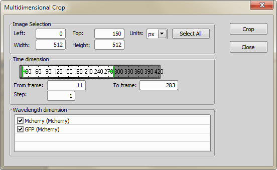
Figure 1654.
A red rectangle surrounding the current image appears when the Crop ND command is called. Move the window aside and adjust the rectangle size and position by mouse. The position and dimensions of the selection are indicated in the window. Everything that exceeds the red border will be cropped.
The white bar in the Time Dimension section indicates single frames. Move the green sliders to determine which frames are to be cropped. You can also fill the range in the below edit boxes. When the step is set for example to “2”, every second frame will be included in the resulting ND2 file
This dimension can be adjusted equally to the Time dimension. The Z low and Z high values of the green sliders are indicated in the window.
This is done by unchecking the channel that you would like to discard.
When there is an ND2 file that includes more than one XY - multipoint position, this command enables you to separate these points. This results in a number of non-XY ND2 files. The following window appears:
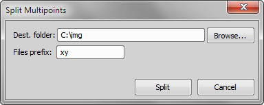
Figure 1655.
Note
If well names are stored inside the ND document, they are automatically used for naming of the resulting files (e.g. A1, A2, … instead of 1, 2, …).
An ND2 file can be composed from a sequence of images. Its structure can be defined via the following window:
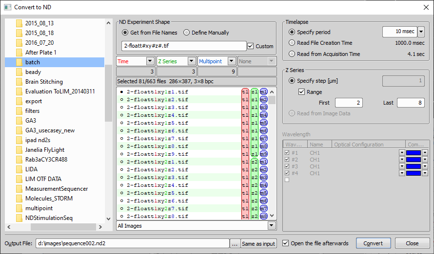
Figure 1656.
Check this option if image names contain information about the the dimensions. Eg.: seq_Z01T01.jpg, seq_Z01T02.jpg, etc.
If the image sequence is not indexed properly, check this option
Set the ND Experiment Shape to the Define Manually mode.
Check this box to enable custom filename filtering. You can use these wildcard characters: “#” matches any digit and “?” matches any character.
From the four pull-down menus, select dimensions to be created. Set the dimensions of ND2 file (Time, Z Series, Wavelength, Multipoint). Specify number of dimension frames in file sequence in the field below. This option is enabled for Define Manually option.
This portion of the window displays a list of all available files. Select the file which will represent a first frame in ND2 file by double-clicking its name or click on the point before the file name.
Set Timelapse period value. Specify the exact value or select to use File Creation Time or Acquisition Time.
Set the Z Series step as a value (µm) or select to use the Z Series step from Image Data.
Define name of the channel. Define the optical configuration name. Choose one of the seven predefined colors or brightfield option as a color of the channel. You can also select the [More] option to define a custom channel color.
If checked then the created ND2 file is opened in the application after the conversion.
Create the ND2 file according to the given properties.
How To
This is the easiest way of creating the ND2 file. All you need to have is a properly indexed source data, which typically means to have sequence of images named like this:
prefix index1 string index2 string index3 .. e.g.: “seq_Z1T1”.
string , prefix - is recognized as any combination of letters. “seq_Z” stands for a prefix and “T” for a string in the example.
Note
It is possible to use the filenames in the form [*010101.*] with [Create ND File from File Sequence] dialog to automatically create ND file with the dimension coordinates specified by the filenames.
Set the ND Experiment Shape to the Get from File Names mode.
The Timelapse properties enables you to set the time between images manually (specify period), or to count the time from file attributes (Read File Creation time), or use the records stored inside the files captured with NIS-Elements (Read from Acquisition Time).
The Z-Series properties requires to define a z-step. This can be filled in manually or let the system read it from the image data.
You can define the Wavelength properties: the name, the color, and the optical configuration that was used for capturing each channel.
If there is an image sequence which is not indexed properly, the ND2 file can be created manually.
Set the ND Experiment Shape to the Define Manually mode.
Saves information about a sequence of images to a JSON file. This file can then be processed as an ND2 file without actually creating one. This is useful when conversion to ND2 would copy lots of image data (hundreds of GB), and especially when the file is to be processed further more in NIS-Elements (e.g. Deconvolution, Denoise, ...) which involves saving. Therefore the JSON file format is a transient format with limited functionality.
The options of the dialog correspond to the File > Import/Export > Create ND File from File Sequence command.
All frames of an ND2 file can be saved as single image files by this command. Tiff and JPEG2000 file formats are supported. This window appears:
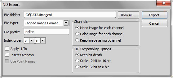
Figure 1657.
Browse for and select a folder to save a file into.
Specify the new exported file type.
Enter a text to to be used at the beginning of the file names.
The order of letters corresponding to dimensions included in the ND2 file can be adjusted. (c stands for Channels)
This option modifiest the exported image data by applying the current LUTs settings.
This option merges all visible layers (binary, annotations, ...) and inserts it to the underlying image data. If this option is used, the images are always exported as RGB images.
There are three available ways to save the ND2 file channels:
Each channel is exported as a mono image and indexed “c1, c2, ...”.
Each channel is exported as an RGB image and indexed “c1, c2, ...”.
This option keeps the channels layout of the original ND2 file.
When saving a tif file, you can choose to keep the original bit depth of the new file, or to rescale it.
How to export an ND2 file
Tip
To reduce the size of an EDF file which usually contains a Z map and other information, the user can use this command with Apply LUTs and Keep image as Multichannel on.
Exporting the ND document to the TIFF file. Enables the user to set the Output, Index order, TIF Compatibility Options and Channels.
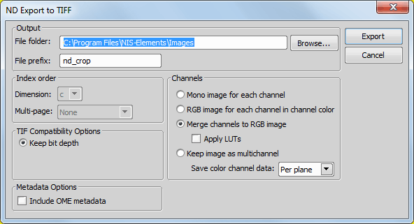
Figure 1658.
Dialog window options are similar to File > Import/Export > Export ND Document.
This option can save the color channel data per plane or per pixel. If you are using a 3rd party software which cannot open your Per pixel exported TIFF files, choose the Per plane option and export them again.
Similarly to the File > Import/Export > Export ND Document command, you can save more ND files at a time as single image files by this command. Following window appears:
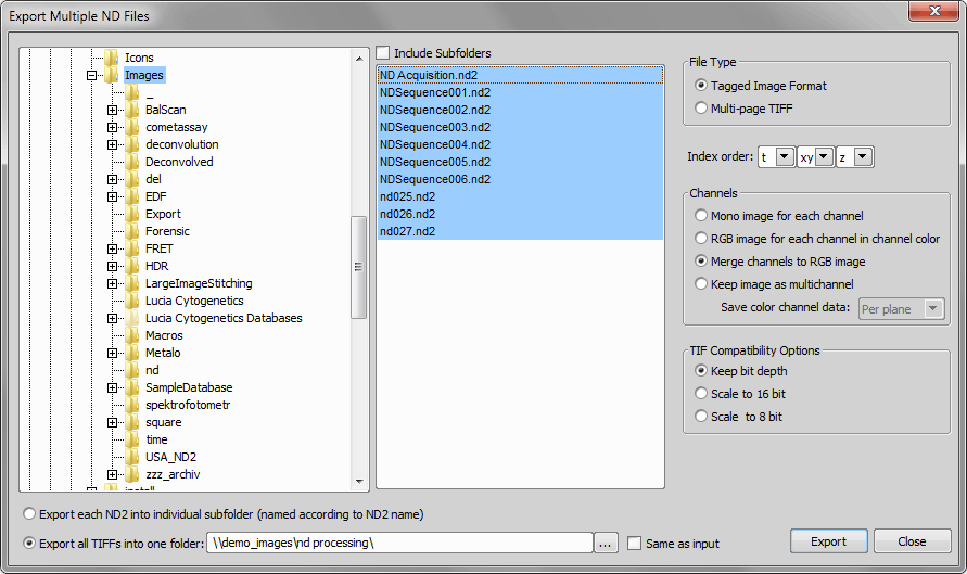
Figure 1659.
Select a folder to save a file into.
Specify the new exported file type.
The order of letters corresponding to dimensions included in the ND2 file can be adjusted.
There are three available ways to save the ND2 file channels:
Each channel is exported as a mono image and indexed “c1, c2, ...”.
Each channel is exported as an RGB image and indexed “c1, c2, ...”.
This option keeps the channels layout of the original ND2 file.
When saving a tif file, you can choose to keep the original bit depth of the new file, or to rescale it.
Exports the images of each ND2 file into individual subfolders.
Exports all the TIFF images of all the ND2 files into one folder, that you can specify, or you can use the Same as input option, to define the path to the folder.
This command imports a DICOM file and converts it to an ND2 file.
This command imports a NEX file and converts it to an ND2 file.
Acquires images from TWAIN compliant devices (scanners, digital cameras etc...). If you have more than one TWAIN compliant device installed, the system prompts you to select the required one. Before you actually acquire the image, usually, you can adjust some scanning properties in the scan setup window. For details, please see the manual of your TWAIN compliant device. After the Acquire command has been performed, the image named Acquired 01 opens. To save it, select File > Save As. If you have acquired a series of several images without saving, the file names are numbered (Acquired 01, Acquired 02, ...).
Note
This command is available only in the 32-bit NIS-Elements application.
Selects a source for acquiring via the Twain driver interface. Select the device, you want to use and press . See also: File > Import/Export > TWAIN.
Note
This command is available only in the 32-bit NIS-Elements application.
This command exports numerical values of the selected image area to the clipboard.
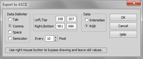
Figure 1660.
Pick the delimiter to be inserted after each value.
Edit the rectangle selection area by specifying the top left and bottom right corner position of the rectangle.
Choose the value type to export.
You can reduce the amount of data by skipping some pixels. 'N-1' pixels are skipped.
You can view the 3D representation of exported pixel values. Click this button and a new dialog containing the graph appears.
After clicking , your data is exported to clipboard. Paste it to any text image.

This command saves the current image (live or static) automatically according to the defined settings. The destination path, file format, file name prefix and other options can be set via the File > Open/Save Next > Save Next Options command. Click the Save Next command and the following window appears. Press the button to save the current image.
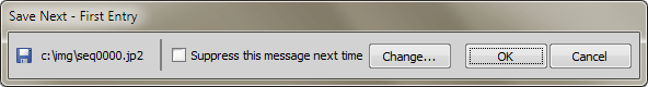
Figure 1661.
The destination path and the name of the image that is about to be saved is displayed in the window.
If you check this option, next time you invoke the Save Next command, the window will not appear and the image will be saved right away.
This button calls the Save Next Options window where all the settings can be adjusted. See File > Open/Save Next > Save Next Options for further information.
Grabbing window
If instead of the Save Next window the grabbing window appears, it means the Show grabbing dialog before saving option is selected in the Save Next Options window (File > Open/Save Next > Save Next Options). This window enables you to define the way of capturing of the current live camera signal. Set the averaging, integration, bit depth, and shading correction and then press Capture.

Figure 1662. The Grabbing window
This command is enabled only if the File > Open/Save Next > Save Next command was used for automatic saving of images. If an image was accidentally saved (by pressing Enter), and you wish to delete it, use this command.
This window enables you to configure the File > Open/Save Next > Save Next command properties.
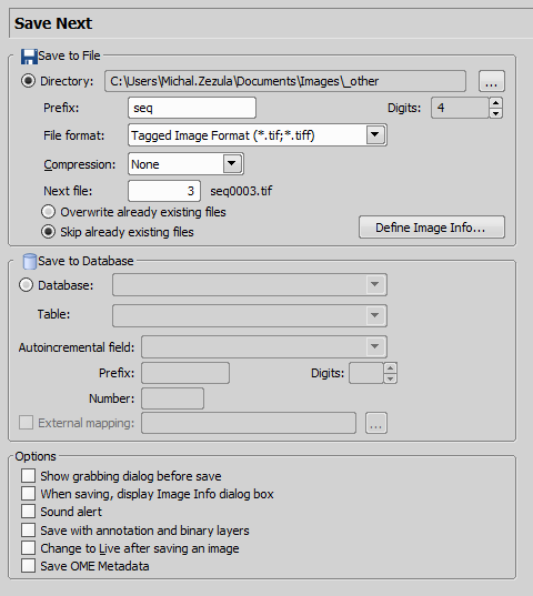
Figure 1663.
Defines name of the file that will be automatically generated. Lets assume, that you have selected - Directory: c:\images; Prefix: seq; Digits: 4; File Format: JPEG2000. Then, by calling the File > Open/Save Next > Save Next command, an automatic file named “seq0001.jp2” is generated and saved to the "c:\images" directory. When pressing Enter again, the file “seq0002.jp2” is saved to the same directory etc.
Displays a dialog box, where you can enter some description (jp2 meta-information), that will be saved with every image:
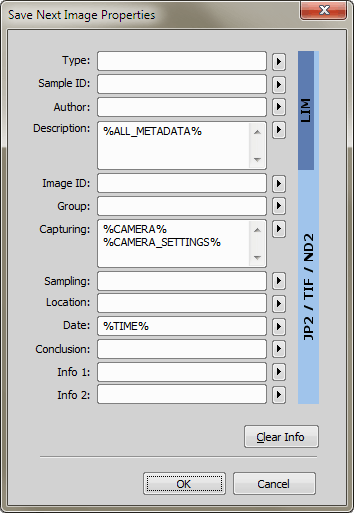
Figure 1664.
Allow or deny rewriting of the images already existing in the default save directory.
(requires: DBASE (Database))
When selected, images are being saved to a chosen database table, instead of saving them directly onto disk.
If you are already connected to some database, select it from the pull-down menu. Else a dialog window appears, which enables you to connect to any database.
Select the database table which the images will be stored to.
Choose which field of the database will be used to store the generated image descriptions.
The image descriptions are generated according to the Prefix, Digits, Number values. Lets assume, that you define - Prefix: seq; Digits: 4; Number: 20. Then, by pressing Enter , the current image is saved to the selected database table and the automatic image description is put into the Autoincremental field of the table. Its name would be “seq0020” in our case. When pressing Enter again, the second record signed “seq0021” is created.
You may create an external *.txt or *.ini file containing mappings that assign table field names to some particular values. These values are automatically filled into the database records when the Save Next command is called. Please, see the comments below for an example.
Note
External mapping example - The *.ini file content may be:
[Table 1]
Author=Jack Sparrow
Experiment number=12
Sample=Malus sylvestris
It means: When saving images to the database table named “Table 1”, the fields of Author, Experiment number, and Sample will be filled with the specified values.
Before an image is saved the Grabbing dialog box is shown. Selecting this option enables you to define the way of grabbing (with/without a shading correction, averaged etc).
You can change the default image information (jp2 meta-information) right before saving.
If checked, a short tone from your PC speaker is played every time the Save Next command is used.
If checked, images are saved together with the binary and annotation layer.
After saving a single image, a Live image is displayed immediately.
OME metadata can be saved with the TIFF file to increase the TIFF file compatibility (e.g. proper channel designation).
See also Supported File Formats.
Pressing this button restores the default settings of this window. All your changes will be lost.
Confirms all the changes and closes the window.
Discards all the changes and closes the window.
Saves the changes which are applied, bud the window remains opened.
Displays relevant help page.
The system tracks the opening and saving operations and then tries to open the 'previous' image in your working directory. Example: when you open image 'seq4.lim' by File > Open command, this command will open 'seq3.lim' image. Let's suppose that seq1.lim, ..., seq100.lim images were saved in the same directory.
The system tracks the opening and saving operations and then tries to open the 'next' image in your working directory. The behaviour of this command differs:
When you set some sorting, filtering, or grouping in Organizer (for both DB records and files), and then open an image by Organizer, the applied sorting is maintained also for the OpenNext command. Furthermore, the sorting criterion is copied to the File > Open/Save Next > Open Options.
When you opened an image by the File > Open command (does not matter if in the Organizer or Image layout), the OpenNext command uses settings of the File > Open/Save Next > Open Options. It does not influence Organizer when these settings are changed.
The system tracks the opening and saving operations and then tries to open the 'first' image in your working directory. Example: when you open image 'seq4.lim' by Image File > Open command, this command will open 'seq1.lim' image. Let's suppose that seq1.lim, ..., seq100.lim images were saved in the directory.
The system tracks the opening and saving operations and then tries to open the 'last' image in your working directory. Example: when you open the image 'seq4.lim' by Image File > Open command, this command will open seq100.lim image. Let's suppose that seq1.lim, ..., seq100.lim images were saved in the directory.
This window enables you to configure the File > Open/Save Next > Open Next command properties.
Specifies the directory with files to open.
Filters the files to open by the image format.
This pull-down menu enables you to select one of the image properties as the ordering criterion. The button toggles the alphabetical order.
Filters the files to open by prefix. You can click  to show advanced filtering options window. The
  button turns the advanced filter on/off.
Displays the name of the file that will be opened after calling the function next time. You can see its name on the right side of the box.
(requires: DBASE (Database))
At least one database must be connected in order to enable this option. Select a database from the list. A database can be created by the Database > New Database command.
The other options are analogical to the ones described above.
Pressing this button restores the default settings of this window. All your changes will be lost.
Confirms all the changes and closes the window.
Saves the changes which are applied, bud the window remains opened.
Discards all the changes and closes the window.
Displays relevant help page.
Merges images displaying the same scene into one image. Each of them is usually captured under different illumination and using different optical filters and different camera settings. It combines color planes stored in separate files into one RGB image. The Merge Image Planes dialog box appears:
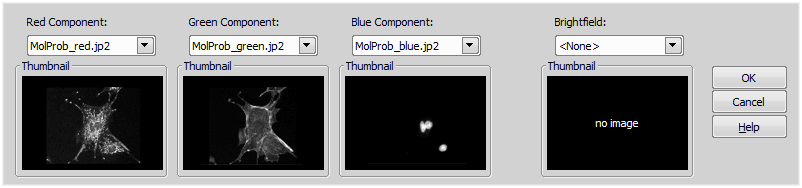
Figure 1665.
The function can take up to three monochrome (fluorescence) images and one color/monochrome (bright field) image. If a color image is inserted into one of the mono channels instead of the monochrome one, the appropriate image component is extracted. The bright field can be either color or monochrome. Monochrome images are transferred into the appropriate color components of the result image which is then blended with the bright field using a special formula. Each source image can be skipped if the user selects the <None> option. If bright field is skipped, the source components can be later easily extracted from the blended image by the Image > Convert > Extract Component command. If the source images are of different sizes, all of them are stretched to the maximum size - images acquired with a different camera binning or resolution can be merged.
Selects a source image (must be opened in NIS-Elements) for defined component.
Selects a source image for bright field.
Combines all opened image files to form one ND2 file. However, reasonable results will be achieved only if the format (size, number of dimensions, etc.) of the images match.
Note
If channel properties of files which were captured by different cameras match and these files are merged, the “acquisition details” meta-information is merged as well and one of the camera names is omitted.
Please see File > Image Properties.
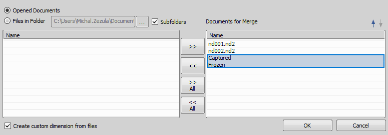
Figure 1666. Merge Opened Documents window .
Dialog Options
The result will contain a Custom dimension. Each of the merged files will form one loop of this dimension. Use this option when merging Time-lapse files which would otherwise form a single-dimension image sequence.
Merging Rules
The following rules are applied when merging (ND2) images.
If multiple images are processed, only two images are merged at a time. After the first two images are merged, the resulting ND2 file is merged with the 3rd image, etc.
It would be easy for the algorithm to take the sum of all frames and put it in a row one after another. However, the algorithm tests all frames for similarities and tries to reduce the final frames count.
Example: Merging of two single-frame RGB images results in a two-frame RGB ND2 file. However, merging of one single-channel (blue) image with a two-channel (red, green) image results in a single-frame RGB image (in other words, the system prefers one-frame three-channel image to three-frame single-channel image).
Two ND2 files both containing Z-Stack can be merged if only the Z-stack acquisition details (number of frames and their Z-positions) match. A Z-stack ND2 image can be combined with a single-frame image, the single-frame will be placed to the top, home or bottom position according to its absolute Z position (written in metadata).
Note
The tolerance for Z-stack merging was increased to one half of the Z-step size, or at least to 0.1um.
Example: Image A: a single-frame image; image B: an XY+Z ND2 file.
If images A and B are merged, it will force one extra XY frame to be created in the resulting ND2 file. However, in this extra XY frame, only one Z-frame can be filled with the contents of Image A (According to the previous rule). Other Z frames will be filled with dummy (black) frames. In other words: dummy frames are created automatically if the ND2 file structure requires it but the image data are not available.
When merging XY (multipoint) dimension, XY points with matching names will be merged to one point regardless of their XY coordinates. This enables you to influence the way how XY points will be merged: points with matching names are always merged together while points with different names are merged into one only if the XY coordinates match.
Caution
This rule does not apply to default point names (#1, #2, etc.) - when default names are used, only points with matching position are merged.
Creates large images from a sequence of files that were captured separately. The following window appears:
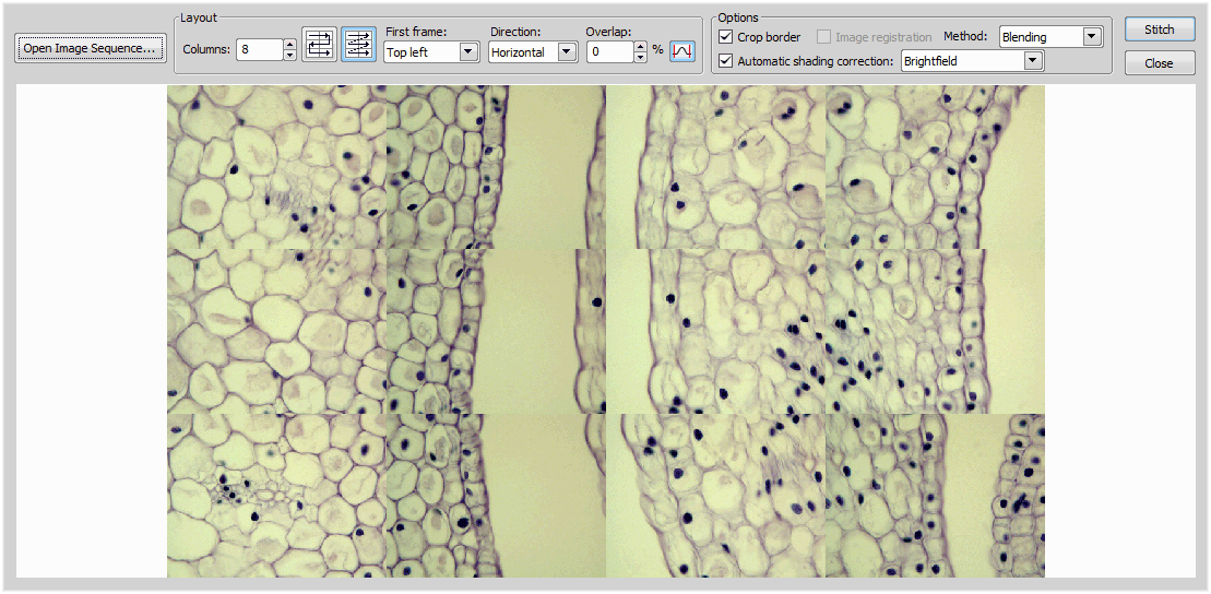
Figure 1667.
This command opens the Image Properties dialog. The dialog appearance may vary according to the type of image. In case you are inspecting an ND2 file properties all the following tabs are accessible.
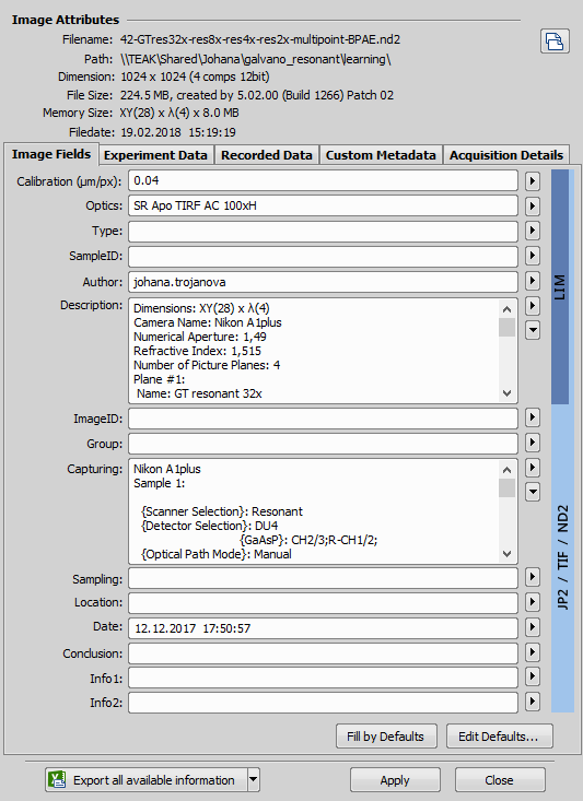
Figure 1669.
Displays the file properties which are provided by the system. Among these properties you can find the file name and location, dimensions of the image, file size, and file date. The version of NIS-Elements including the build number in which the image has been saved is also stored in the image metadata.
The software can determine whether the current image was modified after acquisition. To indicate it, a green text “Original” or a red text “Modified” appears in this dialog.
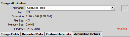
Figure 1670. Image Attributes of a cropped image
The “Modified” text has a different meaning depending on its placement in the dialog:
General changes of image attributes like size, bit depth, number of frames.
The metadata mentioned on this tab have been changed.
Click the button to update status of all image frames. Changes in raw image data will be detected for each frame.
Note
Image authentication can be turned off via the Edit > Options  command.
 Copy Full File Name to Clipboard
 Full path to the current image file is copied to clipboard.
This button exports the data of all tabs at once. Select the destination where to export the data. See also Exporting Results.
This tab appears for all image types. These fields have changeable content. The fields are related to better file recognition, so you can for example specify the image ID, enter any description you like, write you own conclusion and many more. The line on the right side of the fields indicates relevance of the fields to file formats. LIM files use only the upper fields. JP2, tif and ND2 files contain all the fields.
Default values can be predefined by the user (they will be prefilled every time a new image is being saved). Insert these values in the current table by the Fill by Defaults button.
Press this button to open a Default window. Specify all the default content. You can edit all fields. The content can be relative - every time you click the Fill by Defaults button, the current image data will be used, or you can enter fixed content.
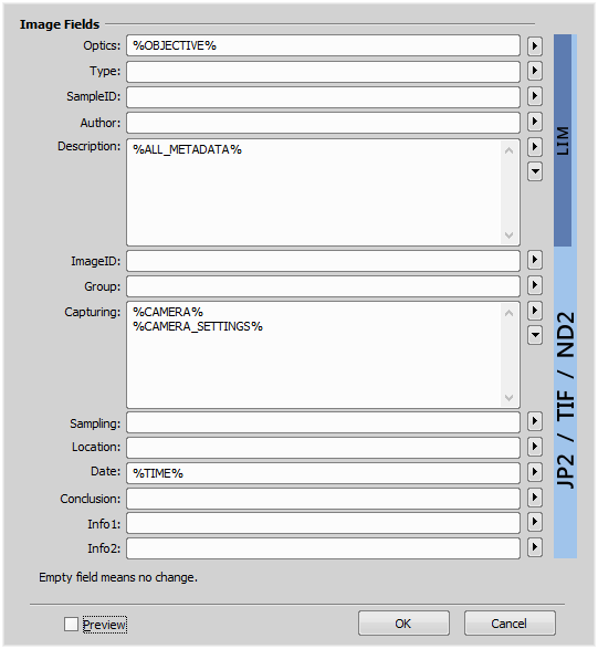
Figure 1671.
 , Substitutional keywords
 The system enables the user to insert some predefined keywords inside the Image Information table. When saving an image, the keywords are dynamically replaced according to the current system state. E.g. the current objective name can be inserted:
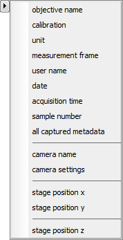
Figure 1672.

The Description and Capturing fields may contain many rows of text. Use this button to view/edit it in a separate resizable window.
This tab appears when you are working with ND2 files. The experiment data tab displays the information about the performed experiment. Provides a summary information about the ND experiment process: if the ND2 file contains spectral, time or z-stack loops, settings of all available dimensions are included.
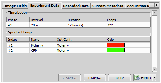
Figure 1673.
The calibration of the Z axis may be modified.
If the ND2 file contains only one phase, the interval between the time loops may be modified.
New step value affects the Time Loop parameters.
Reuse the current ND image setting for creating a new ND2 file. The ND Acquisition window appears with the experiment defined. You can start the new ND acquisition experiment by pressing the Run Now button.
This button exports the data to clipboard, MS Excel application, or an external *.txt file. Select the export output from the pull-down menu next to the button.
The Recorded Data tab contains a table with information about single frames ordered subsequently:
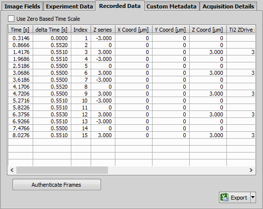
Figure 1675.
Sets acquisition time of the first frame to 0 and adjusts all other time stamps relatively to their time offset from the first frame.
Time when the frame was captured in sec. It is counted from the experiment start.
Time difference between adjacent frames.
Index number of the frame.
Z position of the frame.
Other device data selected for recording during ND acquisition.
See Recorded Data.
Displays performed user events during acquisition.
Press the ... button to open the Edit Events window.
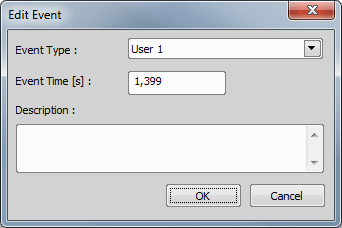
Figure 1676.
Select type and time of an event and append an arbitrary description.
Performs authentication of all image frames. Frames are tested whether they have been modified after acquisition or not. The Enable authentication option must be turned ON in Edit > Options , otherwise this button is hidden.
This button exports the data to clipboard, MS Excel application, or an external *.txt file. Select the export output from the pull down-menu next to the button.
Any custom-defined metadata can be stored inside ND2 documents. This metadata can be defined in Image Properties, ND Acquisition and JOBS.
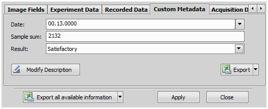
Figure 1677.
 Add/Modify Description
 Opens the Modify Description dialog window where metadata can be altered.
This button exports the metadata to MS Excel, external *.txt file or to clipboard. Select the export output from the pull-down menu next to the button.
This tab displays information about the hardware settings used to capture the image. The following values can be displayed:
| Camera name |
| Optical configuration name |
| Microscope name |
| Emission and Excitation wavelengths of each channel |
| Channel modality of each channel |
| Refraction index and numerical aperture of the objective used |
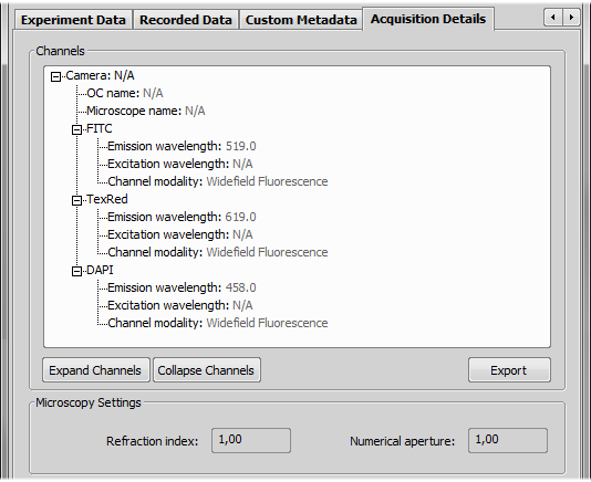
Figure 1678.
Use these buttons to expand or collapse the tree with channel descriptions.
Click the button to unlock the right column where you can edit information about the channels. Select new values from pull-down menus (Channel modality) or double-click the fields to edit them (emission wavelength, excitation wavelength, ...).
Press this button to save the acquisition details to a .txt file. A standard Save As window appears.

Prints the current image. The Print dialog box appears.
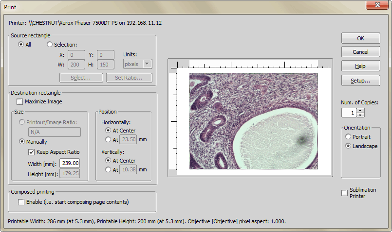
Figure 1679.
Print Window Options
Shows the currently selected printer.
Specify the portion of the image you want to print.
Prints the entire image.
Specifies a rectangle within the current image only which will be printed.
Specify how the image will be arranged on the page.
Printed image will match the maximal printable area. This depends on the printer type and actual settings.
Allows you to set size of the image on the printed page.
In case of calibrated images, a scale factor can be used to define the printout picture size. The value defines the ratio between the printout size and the real image size. For example, the current image dimensions are 640x480 px and the calibration is 1.5 µm/px. Set the Printout/Image Ratio to “100” and the printout size will be (640*1.5*100)x(480*1.5*100) µm = 9.6x7.2 cm.
Allows you to set image width and height manually.
If checked, height of the image is automatically recalculated to preserve the height/width ratio of the original image.
Specify the image width (in mm) on the printed page.
Specify the image height (in mm) on the printed page.
Allows you to set position of the image on the printed page. The At Center option centers the printout horizontally/vertically, the other option allows you to specify a margin in the X/Y axes directions.
Prints multiple images on one page. Check this option and press . The window will close but nothing is sent to the printer. Open another image and run File > Print again. The current image is added to the page. The print window will behave this way until you select the Print composed page option (which appears in the place where the check-box used to be).
Specifies the number of copies you want to print.
Choose the paper orientation, “landscape” or “portrait”.
This option optimizes print for sublimation printers.
This button opens the printer settings window.
This command runs the Report Generator. Please see Creating Reports.
Creates a new report from the selected report template. See Report Templates.
This command runs the Report Generator and opens an empty report template. Please see Report Templates.
This command runs the Report Generator and displays a dialog window for selecting a report file (rpt, rtt) to be opened.
This command opens a window for sharing and managing the shared reports and templates. Users with the right to Modify shared reports can import, remove, and edit any of the shared reports and templates. Users without this permission can only use them to create reports of their own.
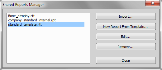
Figure 1680.
This button adds a report or a report template to the list of shared reports. A standard open-like window appears. Select the report to import to the list.
Note
The imported files are copied to NIS-Elements application data directory. The original file is not connected to the list of shared reports.
If a report template (*.rtt) file is selected in the list, the button enables you to create a new report out of it. The Report Generator opens.
Selected reports/report templates can be modified within the report generator using this button. Users with the Modify shared reports right can modify them and save the changes. Other users can save the modified reports to a new file.
Users with the Modify shared reports right can remove a selected report/report template from the list.
This command creates a new report, and inserts the current image to the report page. If performed repeatedly, the images are placed one after each other to a single report. Please see Creating Reports.
Opens the selected file. Up to 16 most recently opened files are remembered in the Recent Files list.