

Select the shape of ROI to be drawn.
Draw the ROIs.
Click the Finish button. The toolbar will be closed.
In the Windows search box on the taskbar, type regedit. Then, select the top result for Registry Editor (Desktop app).
Navigate to
Computer\HKEY_LOCAL_MACHINE\SOFTWARE\Laboratory Imaging\Misc.In the Misc folder execute Edit > New > Key and name it Tracking.
Being inside the Tracking folder, execute Edit > New > DWORD (32-bit) Value and name it OrigSegmentation.
Double-click on OrigSegmentation and change its Value data to 1 and click .
Restart NIS-Elements, and switch to Original Method under the
 Auto Detect tool.
Stim. Point - sets current drawing tool to stimulation point.
Stim. Line - sets current drawing tool to stimulation line.
Free Line - sets current drawing tool to free line.
FCCS Point - sets current drawing tool to FCCS point.
Hold the Ctrl button and select multiple ROI objects by mouse.
Click on the
 Connect button.
All ROIs which overlap will be merged together.
Press the Advanced GUI button. The Segmentation control window appears.
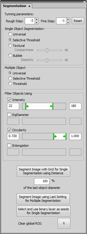
Figure 1818.
Use the Auto Detect or the Auto Detect All buttons to create one or more ROIs at once.
Click on an object in the image which you want to detect. A color border outlines the object. Scroll the mouse wheel to adjust the Rough Step parameter (or hold down the Ctrl key and scroll the mouse wheel to adjust the Fine Step parameter). Use these parameters to change the shape of the outline border line to fit the best the detected object.
If you are not satisfied with the result, try to change the segmentation method.
Single Object Segmentation MethodsThe Single Object Segmentation methods work when the Auto Detect button is used to detect a single object. The Universal method provides good results in most cases. The Selective Threshold method uses threshold to segment the image. Use the Textural method when you are segmenting images of contrast objects on a smooth background (or vice versa). Change the Compactness parameter to get better results. The Bubble method is useful when images of e.g. long fibre structures are analyzed. This method uses the Elasticity parameter to determine elasticity of the bubble-like border.
Multiple Object Segmentation MethodsThe Multiple Object Segmentation methods work when the Auto Detect All button is used to detect more objects. The Universal method and the Selective Threshold methods work similar as single object methods. The Threshold method uses also threshold to segment the image.
Use the object restrictions to filter detected objects by measurement features. Check the feature and sets its range.
When you are satisfied, press the secondary mouse button in the image. The ROIs are created and numbered. In case you are not satisfied, press the Reset button and start again.
You can also use additional buttons at the bottom of the control window which further expand segmenting possibilities.
This command deselects all defined ROIs within the currently opened document.
This command copies all defined ROIs to clipboard. Use command in the image contextual menu to paste the copied ROIs to a different image document.
This command removes all ROIs touching the image border.
Creates any number of regions of interest. The following tool bar appears:

Figure 1817.
There are the following tools available:
 Define new ROI as Global,
  Define new ROI as Multipoint,
  Define new ROI as Time
 When creating ROIs on an ND2 file, these buttons enables you to select the type of ROI to be used when drawing a new ROI.
 Pointing tool
 The Pointing tool switches the current tool to a pointer mode. Then the cursor has similar functionality as if the ROI editor was is closed.
 Rectangle
 Enables you to draw rectangular ROI.
 Ellipse
 There are several ways to draw an elliptical shape. Invoke the pull-down menu and select between them: Circle, 3pt Circle, Npt Circle, Ellipse, 4pt ellipse. Please see View > Analysis Controls > Annotations and Measurements  for details about the tools.
 Polygon
 You can draw a polygon by the standard Polygon tool.
 Bezier
 Enables you to draw a Bezier curve. Use the tool in the same way as the Polygon tool (just place the points around the area of interest and finish it by right-click).
Auto Detect,  Auto Detect All
 Use the Auto Detect tool to let the system detect an area of similar pixels. A continuous area () or more isolated areas () can be created. Please see ROI > Auto Detect ROI for details about the basic autodetect tool.
Note
You can fine-tune the auto-detection parameters by pressing the Show Advanced GUI command from the pull-down menu. The Segmentation control window appears. Please see ROI > Simple ROI Editor.
Note
In rare cases, multi-object tracking may be slow. Switching to the old tracking algorithm may help. To do so, follow these steps:
Define which tool is used from the pull down menu. The tool is then used when click the button.
 Draw Holes
 A ROI can contain holes as well. Use the Draw Holes button to switch any of the drawing tools to the “holes” mode.
Connect This button merges multiple overlapping ROIs together.
 Clear
Clear This button erases all ROIs.
 Undo,
Undo,  Redo
Redo These buttons enables the user to browse the history of changes made on ROIs.
Caution
The Redo button cannot be used after some manual change is made. For example, if you pressed the Undo button several times to go backward in the history of changes, the Redo button enables you to go forward and revert the change. However, if you press the button and then make some change such as adding a new ROI, the button gets disabled and the “forward history” is deleted.
 Help
Help Pressing this button opens this help page.
 Finish
 When you are finished with creating ROIs press this button to close the editor.
Using Advanced GUI Tool
The ROI Editor enables the user to modify the region of interest. It contains a selection of drawing tools of the Binary > Binary Editor command. See Binary Editor for description of all tools.
(requires: Object tracking)
This command enables the user to edit ROIs in time. See Editing ROIs in Time for further information.

Click and drag to draw the inner circle, then release the mouse button and click and drag again to draw the outer circle. Release the mouse button again and the ring shaped ROI is created in the current image.
This command will use an auto-detection algorithm to determine borders of an object within the image. It switches mouse cursor to the ROI auto-detection mode. A ROI is created after user interaction.
See Mouse Wheel.
This command enables you to convert ROIs of the current image to binary layer(s).
Swaps current binary image with Measurement ROI image.
Note
You can get general overview of working images by using View > Thumbnails.
See Also
Binary > Binary Operations
Replaces all ROIs on the current image with the new ROIs created from the current graticule. This function is recommended to use only with rectangular, circle or simple circle graticule types.
The current ROI(s) are inverted and this inversion is inserted into the image as a new ROI.
If you have deleted some ROIs, this command renumbers all the remaining ones so that numbering starts from 1 and is continuous. Only numbers greater than the deleted ones are renumbered.