Average

Integrate
RAM Capture
Capture Multichannel Image
Capture Z-Series
Capture Timelapse
Capture Multipoint
Live Comparisons


Invoke the Calibration > Recalibrate Objective command and select the Auto option (see Objective Calibration). The Flip and Angle parameters are calculated automatically. However, the Flip option needs to be checked only in rare cases, e.g. when a camera is attached to the bottom port of the Ti microscope.
It is always recommended to Rotate the camera mechanically to get correct rotation of the image. When this is not possible, define how the image frames and XY axes are rotated.
Use the Angle parameter when a motorized XY stage is mounted. E.g. for dragging the stage by mouse within the field of view, stitching, etc. This parameter is not used for manual microscopes - the default value can be left.
You can also use the Get Angle button, which automatically finds the camera angle.
DS-Qi2/Ri2 camera
DS-L3/U3 camera unit
Ni-E / Ci-E / Ni-U microscope
Let's set the averaging to 16x and turn the Acquire > Average > Define Average to Quality option on.
A Quality value is computed for two subsequent averaged images (e.g. AVG(4) and AVG(5)). The quality value is defined as the average difference per pixel in Decibels. It characterizes how much the two images differ. The greater the Quality is, the less the images differ.
If Quality gets greater or equal to the Quality limt or the limit of 16 averaged camera frames is reached, the image is captured.
It is recommended to experiment with the Quality limit value and optimize it for your samples and camera. The default value is 35.
Focus on the first frame of the scene to be captured, click the Next button.
The first frame is captured.
Continue capturing frames by the Next button moving the Z drive after each frame.
Input the Z Step value that will be used to calibrate the Z axis of the ND2 file.
You can turn ON and OFF the Live image by the
 button.
Click the Finish button to close the window. The captured sequence opens.
Focus on the scene to be captured, click on the Next button.
The first frame is captured and the frame number with the acquisition time is appended to the table.
Continue capturing frames by the Next button.
Pressing the button with green arrow freezes the live image. If you press the button once more, the live image appears again.
The Finish button closes the dialog and opens the captured sequence.
Click the Capture Manually command.
Select, whether to include the Z Coordinate information in the resulting ND2 file.
Focus on the scene to be captured, click Next.
The first frame is captured and the frame number with the XY(Z) position is appended to the table.
Continue capturing frames by the Next button.
Pressing the button with green arrow freezes the live image. If you press the button once more, the live image appears again.
The Finish button closes the dialog and opens the captured sequence.
tile overlapping area is ≤ 14 %, or
the image is static for a while.
This command opens the Camera Light Path window:
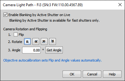
Figure 1694. Camera Light Path
If this function is turned on while viewing a live signal from the camera, a triggered active shutter (e.g. NIDAQ Illumination Device) automatically opens with the camera exposure start and closes with the exposure end.
Note
Only electronic triggerable shutters support this feature - i.e. shutters which do not physically move any of their components but just control LEDs, AOTF, etc., and at the same time have the triggering ability (can be used in Triggered Acquisition or are triggerable virtual shutters of a multilaser).
Define operations to be made to the camera image. See Camera Rotation and Flipping.
Camera Rotation and Flipping
Note
This command is displayed in the main menu only if either of the following hardware is connected to NIS-Elements:
This command acquires an image by the hardware button on a device under predefined conditions, with optical configurations and cameras. All the settings can be defined within a dialog which appears:
Note
Output setting of the capture button is reset to “DSC” after turning off the power of the ECLIPSE Ci microscope main body. Please change it to USB again by the Ni Setup Tool or DS-L3 after restarting the Ci microscope if you want to use device capture via USB in the same way as the last time.
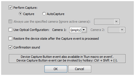
Figure 1695.
Check this item to perform the Capture or the AutoCapture command when the button is pressed on a device.
If multicamera mode is enabled, this option displays primary and secondary camera. Choose which camera is used for image acquisition regardless of which camera is currently active.
Check this item and choose existing optical configuration. If multicamera mode is enabled, you can choose different optical configurations for each of the cameras.
Check this item to restore the microscope settings automatically after image acquisition has finished.
If this item is checked a beep sound is played when acquiring an image has finished.

This command adjusts parameters of the currently used camera. The Camera Settings dialog box appears. Please see Cameras.
Note
After this command is run, the Live image will start automatically. If some processing has been made on the Frozen image, the processing results will be lost.
Displays the live image in the picture window. You can usually define its resolution by the Acquire > Camera Settings command.
Note
Some image operations automatically freeze the image in order to perform operations correctly, e.g. NIS-Elements swaps live and freeze image display mode when preprocessing, transformation and measurement commands are invoked.
Displays the capture-quality live image in the picture window. You can usually define its resolution by the Acquire > Camera Settings command.
Note
Some image operations automatically freeze the image in order to perform operations correctly, e.g. NIS-Elements swaps live and freeze image display mode when preprocessing, transformation and measurement commands are invoked.
This command captures the current scene and displays the image in a new window. See Image Acquisition.

This command captures the current live image and saves it to the View > Acquisition Controls > Auto Capture Folder  according to the File > Open/Save Next > Save Next Options. You can create sequences of images via this command.
The Auto Capture button in the application top toolbar can perform the same function.
Averaging is a good noise-reduction technique. Use this function to set the averaging parameter of the acquisition to the number indicated in brackets. For example, if you are capturing with Average 4x, the software will use 4 frames received from the camera to create one resulting image by averaging their pixel intensities. Averaging reduces the frame rate accordingly.
If turned on, averaging is performed until the Quality limit or the maximum specified frame count are reached. You can change the Quality limit by the Acquire > Average > Define Average to Quality command.
Example
This command opens a window which sets the quality value for averaging:
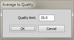
Figure 1696.
The quality value is defined as average difference per pixel per component in Decibels. See Acquire > Average > Average to Quality for explanation.
Integration comes handy for low-signal (dark) scenes. Use this function to set the integrating parameter of the acquisition to the number indicated in brackets. For example, if 4x is indicated in the brackets, the software will use 4 frames received from the camera to create one resulting image by integrating their pixel intensities. Integration reduces the frame rate accordingly.
This commands turn the RAM buffer OFF.
See Also
Capturing to Ring Buffer
Turns the RAM buffer ON, the live image is displayed, a history of frames is continuously saved to RAM.
See Also
Capturing to Ring Buffer
This command performs the RAM capturing procedure. It acquires a time sequence of images according to the Acquire > RAM Capture > Settings. A new ND2 file is created.
The length of the image sequence captured by the RAM Capture feature can be set within this window.
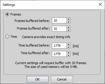
Figure 1697.
Frames buffered before/after represent the captured number of frames before and after you click  Capture. The whole time interval will be included in the sequence and the number of frames and memory size required for the buffer will be indicated below.
Note
If you run the Acquire > RAM Capture > Capture command while in the Frozen mode or with the circular buffer turned OFF, only the frames of the Frames buffered after interval will be captured.
Time buffered before/after represents the exact time interval (provided by the camera) before and after you click Capture. The whole time interval will be included in the sequence and the number of frames and memory size required for the buffer will be indicated below.
Confirms the current dialog settings and closes the window.
Closes the dialog window without saving the current settings.
This command opens the AVI/MP4 Acquisition dialog window enabling to easily capture a movie and save it to the AVI or MP4 format.
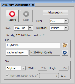
Figure 1698.
This command opens Fast Timelapse dialog window. Specify the setting used for acquisition. Use the Live button or the  button to start or freeze live image. When all the settings (described below) are set properly, press the Apply button and the system will test whether the acquisition can be run safely (e.g. it could warn you about lack of memory). Then press the Run now button to start the fast Timelapse acquisition.
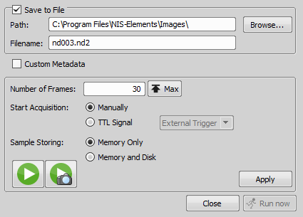
Figure 1699.
Check this item to save the fast Timelapse image to a file after it is acquired. Specify destination folder and name the file below.
Inserts user-defined metadata to the resulting image sequence. Enable the option and select a metadata preset from the pull-down menu. You can also edit metadata presets by the button. See Defining and Setting Metadata.
Define number of frames. If the option Memory Only is selected, you can use the button to determine number of frames which fit to the PC RAM memory.
Fast Timelapse acquisition will be start immediately after you press the button.
This option is available when a TTL input device is connected. Then the TTL signal is used to start the fast Timelapse acquisition.
Select to use a combination of memory and hard disk or just only the memory to store the samples.
Displays a window which enables you to run manual integration. Click the button to begin integrating frames (frame #1 + frame #2 + ...). Click the button to close the window and display the resulting image. You can also make the integration stop automatically by selecting the Stop on oversaturation option. It is possible to integrate any number of the consecutive frames.
Window Options
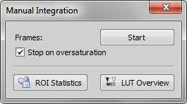
Figure 1700.
Displays the number of image frames integrated so-far.
Starts integrating frames.
Closes the dialog window and displays the integrated image.
When selected, pixel intensities are evaluated after adding each frame. If any of the pixels reaches maximum value, the last frame is discarded and the window closes as if you clicked the button.
These buttons open the corresponding control panel which might be handy during manual integration. See View > Analysis Controls > ROI Statistics  , LUTs - Non-destructive Image Enhancement.
(requires: RT Acquisition)
This command opens the Triggered Acquisition panel where fast camera-triggered experiments can be set up. Please see Acquisition Settings.
(requires: Illumination Sequence)
This window displays the Illumination sequence dialog window. For more information, please see: Illumination Sequence.
This command runs the automatic multichannel acquisition procedure according to the Acquire > Capture Multichannel Image > Multichannel Setup command settings. When the procedure is finished, the resulting multichannel image is opened.
For more information about multichannel capturing see Multi-channel Acquisition description.
Captures a multi-channel image while changing the filters manually. See Multi-channel Acquisition.
This command enables you to set your setup preferences for capturing a multi-channel ND2 file. Please see Multi-channel Acquisition for additional information.
This command enables you to automatically capture a Z-series ND2 file. Please see Z-series Acquisition for further information.
A Z stack sequence of images can be captured manually using this command:
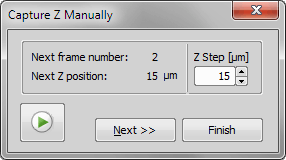
Figure 1701.
Note
The Z Step value can be changed during the acquisition, but only the last value (which is in the field when you click the button) will be written to the image meta-data.
In this dialog it is possible to define Timelapse acquisition. You can simply define delay between two frames or create a much more sophisticated scenario. See Time-lapse Acquisition.
A time lapse sequence of images can be captured using this command:
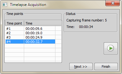
Figure 1702.
This window serves for defining XY(Z) points to be scanned during the multipoint capture experiment. See Multi-point Acquisition.
A time lapse sequence of images can be captured using this command.
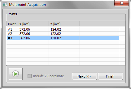
Figure 1703.
Note
Motorized XY(Z) stage is required to perform the multipoint acquisition successfully.
Performs manual user acquisition based on single captured images of an experiment. Press the Capture button to capture each frame. An ND2 file is created from the sequence of captured images after you press the Finish button.
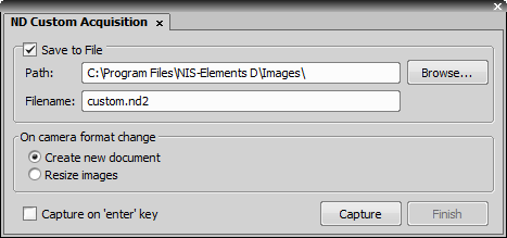
Figure 1704.
Check this item to save the image in a file. Specify the destination folder and name the file.
This option defines an action which should be done when camera format (resolution) has changed during the experiment. There are two possibilities: either a new image is created or the image is resized.
Check this option to assign the Enter key to the Capture action.
Opens the Manual Large Image Grabbing window used for custom large image acquisition. It is useful especially if the user does not know the shape (area) of the sample being acquired, captures it without an overlap or wants to decide at any given moment which parts of the sample will be grabbed.
 Start
Start Starts the image grabbing by capturing the first tile on the current XY position.
Capture Captures a tile on the current XY position and adds it to the large image preview.
Tip
Use the space bar as a keyboard shortcut for capturing.
 Finish
 Finishes the large image acquisition creating a large image document.
Live Turns on the live image.
 Freeze
 Pauses the camera live view.
 Remove the last tile
 Deletes the tile captured last. Only one step back is possible.
 Remove all tiles and start again
 Deletes all tiles captured so far and starts the large image grabbing all over again.
 Auto Capture
 Automatically captures a tile if:
The border of the frame is green during moving, changes to purple when the overlap is ≤ 14 % and turns red when it is completely out (move closer to the previous tile in such a case).
 Auto Shading Correction
 Applies the automatic shading correction to the captured tiles. If this option is turned on and the large image grabbing is finished ( Finish), the selected shading (indicated in the brackets) is applied to the large image. Thus the user can preview the image before creating the large image and decide whether to use the shading correction or not. Click on the  arrow button to choose the type of correction which best represents the background of your sample image.
 Show live and preview windows side by side
 Shows the live window and the preview window next to each other.
 Fit to Screen
 Adjusts the zoom so that the tiles fit the preview window.
 Zoom In
 Zooms the preview window in.
 Zoom Out
 Zooms the preview window out.
(requires: Stage)
This command captures large images using the Macro overview. The scanning is performed the similar way to a manual large image grab, except the meander movements are realized via the stage control. The large image scan procedure scans the specimen in the way of the meander, covering the whole area of the rectangle specified by the user. The rectangle can be specified either by the current position and the number of fields or by specifying the rectangle margins (pressing the appropriate button, the user specifies that the current stage position corresponds to the appropriate rectangle margin). While setting the scanning area, the user can move the stage using joystick. While scanning, the system displays the particular result enabling the possibility to interrupt the process by pressing the Cancel button.
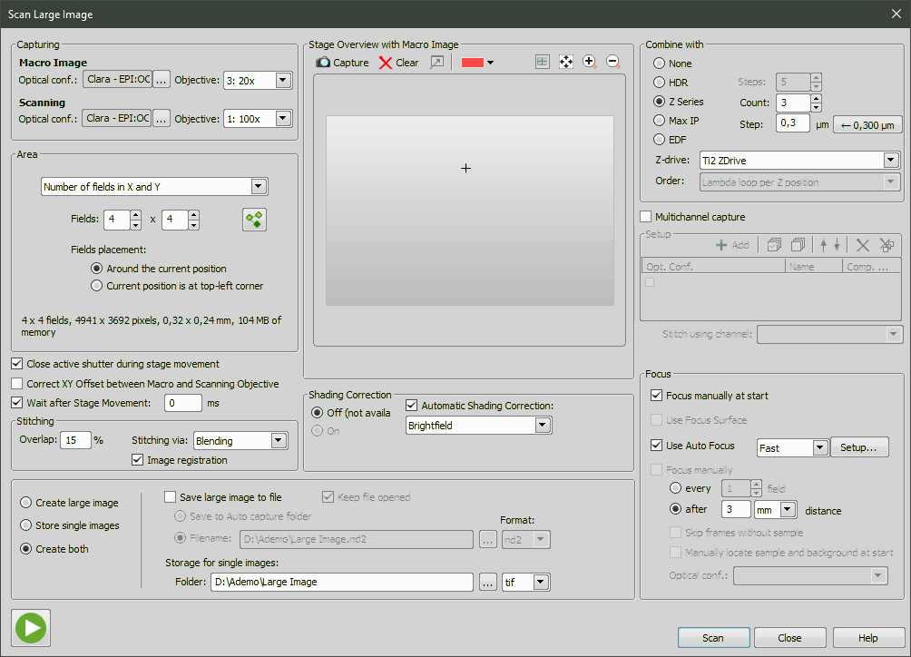
Figure 1705.
Choose one of available optical configurations and objectives which can be assigned for scanning Macro Image and Large image Scanning from the pull down menus.
Note
When you select different optical configuration in the Scanning section and in the Multichannel capture section, then the optical configuration defined in the Multichannel capture section is used for capturing large images.
Select a method used for scanning. Information about resulting image is displayed below.
Defined by
Define additional settings for this selected method:
Set the horizontal and vertical acquisition number of sheets. The information of resulting image are displayed below.
Select the position of the fields in reference to current position.
If you have selected the Left, top, right and bottom limits method for scanning, you have to set following limits:
The arrow buttons set the current position to be the top, right, bottom, or left margin.
The information of resulting image are displayed in between the buttons.
if you have selected the Area of Interest in XYZ Overview method, the area of a large image is calculated from the area of interest defined in the XYZ Overview control window.
Check this item to close the shutter during stage movement.
If checked, XY correction between objectives is used. This concerns the Devices > Objectives XY Offset Setup command.
This delay between captures can be used for sample stabilization, e.g. after XY movement or autofocus. If 0 ms is entered, then is displayed and the user can click this button in order to continue with the next capture.
Choose whether the images will overlap. If you select the Overlap option, set also percentage of one frame overlapping its neighbour and a stitching method. Blending method blends the overlapping image parts and Optimal path method computes a contour in places where two overlapping images are least different and then they are stitched copying this contour (see: Methods Used for Stitching Large Images). Image Registration compares the image texture and automatically adjusts the position of images. If there are pixel-shifts between neighboring images, this function will help. If you select No overlap, the frames are stitched without using the registration algorithm.
This option turns on the shading correction. It is a crucial feature that allows to scan sufficiently homogeneous images. A “Per Optical Configuration” shading correction must be setup beforehand in order for this option to be enabled. Please see Acquire > Shading Correction Panel for further details.
Automatic Shading Correction
To perform the shading correction on captured images automatically without capturing the shading image, check this option and select the type of correction which best represents the background of your sample image. If Automatically per channel is selected, the shading modality method is detected and applied per channel.
After scanning one large image is created. This option is checked by default.
If you select this option, every field of a large image is saved to a separate file so you can perform stitching arbitrary in the future. (For example when 3x3 field array is defined then 9 images will be created). Select type of image from the list of possible formats of single images.
And use the Folder field to enter a folder to save single images in.
Separate single images and also one large image is created at the same time.
Check this item to enable saving of the large image to a file automatically.
Check this item to keep the file opened after it has been saved to a file.
If selected, the captured large image is saved to the Auto Capture folder.
Enter or choose a filename of the new file.
This option defines format of single images or the result image file.
Displays folder where single images are saved. It can be directly edited in the field, or you can look for another folder using the ... button.
Overview of the XY stage is displayed in preview. It will ease the setup of the area setup. Use the following buttons:
You can move the view using the arrows on the sides of the preview.
Capture This button captures a preview image using the Macro Image settings. This image is then displayed in the preview section along with the scan area preview. The settings of the scan area may be modified by dragging the preview by mouse.
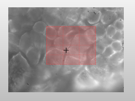
Figure 1706. The Macro image with the Scanning Area indicated
Caution
Size of one frame of the scan area preview is only schematically displayed in dependence on the current zoom of the preview. Since FOV (Field Of View) of the objective selected for scanning can be bigger than indicated within the preview, the area included in the resulting Large Image can be slightly bigger than the actual area settings defined within this dialog window.
 Clear
Clear This button deletes the captured Macro image.
 Fit to Macro Image
 This button zooms at the field of view according to the Macro Image settings (current stage position + the specified objective)
Fit Stage Area This button zooms at the whole area achievable by the XY stage (Stage Area).
Zoom In, Zoom Out Zoom the preview IN or OUT by these buttons.
Note
If there is Nikon DS-U3 / L3 camera connected , the Define using L3 controller button is enabled. This option triggers definition of large image area from the camera pad.
Note
If there is Nikon Ni-E microscope connected, the Define using Ni-E microscope button is enabled. This option triggers definition of large image area from the microscope pad.
Choose how to scan z series. Use the Count value to define number of steps for Z series and EDF. Or use the Step value to define distance between steps in micrometers for Z series and EDF.
Z series will not be used.
Captures a High Dynamic Range image using the selected number of Steps.
Select this option to create a Z stack ND with large image for each Z step. When the Store single images option is selected, a single image is created for every Z step. For example when acquiring of 3x3 fields and 4 Z steps is defined then 36 (3x3x4) images are created.
Note
If a Z-series acquisition is defined within the system, the Count and Step fields are pre-filled with values matching to the Z-Series setup. Otherwise, the values are remembered from previous usage of the window.
Select this option to create the large image as maximal intensity projection focused image.
Large image will be created as EDF Focused Image. See Extended Depth of Focus for further details.
Note
The resulting image can not be displayed as an anaglyph or a 3D surface because the 3D information is not saved with the large image.
Choose which available Z drive is used to acquire the Z series.
Select order of acquisition: either the Lambda loop per Z position or the Z series per channel option can be chosen.
Check to enable multichannel capturing. Even though the window has similar appearance and controls as the window used for ND multichannel acquisition (see Multi-channel Acquisition) the settings is not shared.
Choose which channel is used to stitch the large image. All available channels are listed in the pull down menu.
The application waits for the user confirmation before changing to next channel.
Specify the way of focusing.
This option is used to focus manually after you start scanning.
Check this option to use a Focus Surface instead of automatic/manual focus. If the scanning area is defined by the Left, top, right and bottom limits, the  button appears. This button creates a focus surface based on the Z coordinates of the four boundary definition points.
This option enables you to use automatic focus during the scan. For speed priority of the auto focus select Fast, in other cases choose Legacy. Use the Setup button to display the Auto Focus Setup dialog.
The user will focus manually in the defined focusing frequency.
This option requires to have a shading correction defined properly (see Acquire > Shading Correction Panel). When selected, the application detects the sample-free / background-only image frames and omits focusing on these frames.
Asks the user to locate the sample and sample-free image areas just before the large image scan.
Select an optical configuration to be used for the auto-focus.
Runs live image.
Starts scanning of the large image.
Closes the window.
Displays this help page.
Displays live image in the live window.
See Also
Acquire > Freeze, Acquire > Live - Fast
Splits the screen vertically and displays live image in the left half and the original image in the right half.
Splits the screen vertically and displays live image in the right half and the original image in the left half.
Splits the screen horizontally and displays live image in the top half and the original image in the bottom half.
Splits the screen horizontally and displays live image in the bottom half and the original image in the top half.
Displays the live image in the odd lines and the original image in the even lines.
Displays alternately the original image and the live image in a user-defined rectangle. The rectangle can be defined by dragging the rectangle selection on the screen using the mouse.
Alternates the original image and the live image in a user-defined rectangle. The rectangle can be defined by drawing on the screen using the mouse.
Displays the original image at pixels where the binary image is equal to one and the live image at pixels where the binary image is equal to zero.
Displays the live image in the green component and the original image in the red component.
Displays the difference between the live and the original image.
Please see Shading Correction.