
Length, area, angles, taxonomy, counts, circle radius, and ellipse semiaxes can be measured manually over an image. There are several tools for measuring each feature. The results are being recorded to a simple result table, which can be exported to a file or clipboard. The data can be presented as a graph, too.
Example - Measurement of a Grain Thickness
Run the
 View > Analysis Controls > Annotations and Measurements
  command. The manual measurement control panel appears.
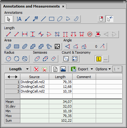
Figure 215.
Place the first line on the top edge of the crystal by clicking into the image. The position of the line can be adjusted while you hold the primary mouse button down. After you release it, the line is positioned.
Repeat this to place the second line on the bottom edge of the crystal.
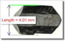
Figure 216.
When finished, an arrow is drawn between the lines, and the result of the measurement is attached. A record with the measurement type and the measured value is added to the results table.
After finishing the measurement (e.g. of multiple grains or other images), select where to export results in the Export pull-down menu.
There are two types of vector objects which can be placed over the image to a separate layer:
Vector objects used to emphasize or label interesting areas in the image, such as an arrow, a text box, etc.
After a measurement object is placed to the image the measured value is appended to the table of results. See Basic Workflow.
Use the  Show Annotations (A) icon on the right image tool bar to display all vector objects in the layer.
Objects of the annotation layer can be selected by mouse. Multiple selection is enabled when the Ctrl or Shift keys are pressed at the same time. The selected objects can be deleted by the Del key. Or, right-click the Show Annotations (A) button to display a context menu containing these commands:
If an ND document contains a time dimension, you can set visibility of any annotation or measurement object throughout the time. Use the  right mouse button over the object and select the Object Visibility command. The following dialog appears.
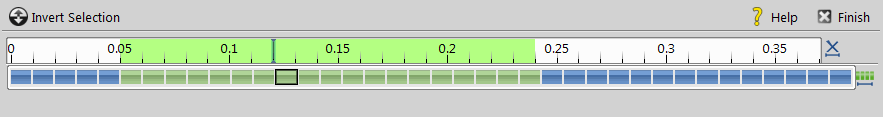
Figure 217. Visibility Settings
Use Shift and Ctrl keys and primary mouse click to select frames over which the object will be visible. Once you define the selection, click  Finish.
Run the View > Analysis Controls > Annotations and Measurements command to display the following measurement tools:
 Measure Free Angle
 Angle between the two connected lines is measured. Click the primary mouse button and drag to draw the first line and release the button. Then use the secondary mouse button click to confirm the first line and repeat the procedure for the second line.
 Measure 2 Lines
 Angle between the two separated lines is measured. Click the primary mouse button and drag to draw the first line and release the button. Then use the secondary mouse button click to confirm the first line. Click the primary mouse button and drag to draw the second line (*).
 Measure Via Reference Angle
 Angle between two lines (one is a reference line) is measured. First use the  Define Reference Angle tool to define the reference line. Then select Measure Via Reference Angle, draw the second line using the primary mouse button and confirm the object by the secondary mouse click.
Define Reference Angle Draw a line in the image (using ) and confirm it using the secondary mouse button or enter a precise value in degrees into the edit box and click .
(*) - If the  Confirm with R-Click button is selected, confirm the object by the secondary mouse button.
 Polygon
 Polygon area is measured. Draw a polygon by clicking the primary mouse button inside the image. The secondary mouse button or a double-click will place the last node of the polygon and close the object (*).
 Rectangle
 Rectangle area is measured. Draw a rectangle holding down the primary mouse button (*).
 Ellipse
 Ellipse area is measured. Draw a circle holding down the primary mouse button. Click on the edge of the circle and drag to form an ellipse (*).
 5 Point Ellipse
 5 point ellipse area is measured. Define five different points into the image using the primary mouse button. The system automatically interpolates these points and finishes the ellipse (*).
 4 Point Ellipse
 4 point ellipse area is measured. Define four different points into the image using the primary mouse button. The system automatically interpolates these points and finishes the ellipse (*).
 Auto Detect
 Area of the detected object is measured. The system automatically detects a homogeneous area around the clicked point. Tolerance (size of the area) can be adjusted by rolling the mouse wheel or by using the Page Up/Page Down keys. Confirm the object by the secondary mouse click.
 Select Binary
 Area of objects detected on the binary layer is measured. The system automatically detects a homogeneous area on the binary layer around the clicked point.
(*) - If the Confirm with R-Click button is selected, confirm the object by the secondary mouse button.
 2 Points
 Distance between two points is measured. Use the primary mouse button to define the starting and ending point (*).
 Simple Line
 Line length is measured. Click and hold the primary mouse button over the starting position and drag to the ending position and release the button (*).
 Horizontal,
  Vertical
 Horizontal/vertical distance between two lines is measured. Click the primary mouse button over the starting point and move to the ending point and click again (*).
Note
You can modify default length of the measurement lines. Click the measurement line and resize it by mouse. The new length will be remembered and used for the next measurement.
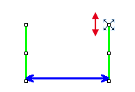
Figure 218. Resizing of the measurement line
Alternatively, you can hold the mouse button when placing the first measurement line and draw the line long as you like. The default length will not be affected by this action.
 Parallel Lines
 Distance between two parallel lines is measured. Click the primary mouse button over the first point of the line, move to the second point of the line, adjust the position of both points and confirm it using the secondary mouse click. Then move to the position of the second line and click the primary mouse button, adjust its position and confirm the whole measurement by clicking the secondary mouse button.
 Polyline
 Polyline length is measured. A polyline consists of several line segments. Use the primary mouse button to draw the line segments. Each mouse-click creates a new node. Complete the total length definition by the clicking the secondary mouse button (*).
 Crosses
 Distance between two crosses is measured. Click the primary mouse button to define two points between which the distance is measured (*).
 Auto Default
 Distance between two points estimated by the computer is measured. Click and hold the primary mouse button, drag and release the button to draw the line. The system automatically detects the sharpest changes of the pixel intensities and adjusts the point position (*).
 Auto Outer
 Distance between two points estimated by the computer is measured. Click and hold the primary mouse button, drag and release the button to draw the line. The system detects several sharp changes of the pixel intensities and selects the first and the last one as the measurement points (*).
 Auto Inner
 Distance between two points estimated by the computer is measured. Click and hold the primary mouse button, drag and release the button to draw the line. The system detects several sharp changes of pixel intensities and selects the second and the next to the last one as the measurement points (*).
 2 points on XY stage
 Measures the distance between two points on a live image which do not fit the camera FOV. Click the primary mouse button to mark the first point, move the stage to the second point on the sample and click in the image to mark the second point.
(*) - If the Confirm with R-Click button is selected, confirm the object by the secondary mouse button.
Open an ND2 file containing a Z dimension.
Run the
View > Image > ND View > Slices View  command to display the image in Slices View.
Select a Z plane (use the mouse wheel) on which the first point lies. Click the primary mouse button to mark that point (crosshair is shown). Confirm its position by the secondary mouse click. The color of the crosshair changes.
Select a Z plane on which the second point of your measured line lies. Place the second crosshair as in the previous step and confirm it using the secondary mouse click.
Measured value is written into the results table of the
View > Analysis Controls > Annotations and Measurements window. Properties of the measurement line and text can be adjusted using the  Properties command found in the context menu over the line.
Open an ND2 file containing a Z dimension and run the
Applications > EDF > Create Focused Image  command.
You may switch to
 Show EDF 3D Surface View, or stay in the Show EDF Focused Image view which appears automatically. The 3D Measurement behaves the same way in all of the views.
Define both points of the measured line by the primary mouse click. Measurement is performed automatically and the length is displayed over the line and in the results table of the
View > Analysis Controls > Annotations and Measurements window.
 Length 3D
 (requires: Extended Depth of Focus)
This tool performs interactive 3D measurement on ND2 files which include the Z dimension.
Measurement on Slices View
Measurement on a Focused Image, Surface View
 Circle
 Radius of the circle is measured. Click and hold the primary mouse button and drag to create a circle and release the button. Adjust the circle size and position (*).
 3 Pts. Circle
 Radius of the circle is measured. Define three different points into the image using the primary mouse button. Adjust the circle size and position (*).
 N Pts. Circle
 Radius of the circle is measured. Define as many points as you like into the image using the primary mouse button and confirm the object by the secondary mouse click. The circle is created by interpolating the defined points. Adjust the circle size and position if needed.
 Ellipse
 Ellipse semiaxes are measured. Click and hold the primary mouse button and drag to create a circle and release the button. Click on the edge of the circle and drag to form an ellipse. Adjust the ellipse size and position if needed (*).
 5 Point Ellipse
 5 point ellipse semiaxes are measured. Define five different points into the image using the primary mouse button. The system automatically interpolates these points and finishes the ellipse. Adjust the ellipse size and position if needed (*).
 Free Rectangle
 Rectangle semiaxes are measured. Click and hold the primary mouse button and drag to create a rectangle. Adjust its size, position or rotation (using the green anchor point) (*).
(*) - If the Confirm with R-Click button is selected, confirm the object by the secondary mouse button.
Click the
 icon.
icon.Use the secondary mouse click over the results table and select Taxonomy Options.
In the Taxonomy Options window, define the number of classes (from 2 to 70) and the way of inserting markers:
On left button downInserts a marker to the current cursor position after a mouse click. If this option is selected, the function keys switch between the classes. In this mode, the Fn keys works for switching between classes.
On Fn key at cursor positionAfter the Fn key is pressed, the count is performed and the corresponding marker is placed to the current cursor position.
On Fn key at screen centerAfter the Fn key is pressed, the count is performed and the corresponding marker is placed to the center of the image view.
On Fn key at cursor position, no marker insertedAfter the Fn key is pressed, the count is performed and no marker is placed.
Start the count according to the Taxonomy Options setting.
Note
The keyboard Fn (function) keys F1 - F10 can be used as a shortcut for classification/class selection. Since there are 70 classes available, certain key combinations must be pressed in order to select/classify the right class:
Key Combination Class Number Fn n Ctrl + Fn 10 + n Alt + Fn 20 + n Shift + Fn 30 + n Ctrl + Alt + Fn 40 + n Ctrl + Shift + Fn 50 + n Shift + Alt + Fn 60 + n Perform the measurement until all classes are counted.
 Count
Count Click inside the image to insert counted points. The current count is shown next to each point and its position and number is recorded. Finish counting by the secondary mouse click.
Taxonomy This tool is used to manually count objects of up to 70 classes.