


 Applications > HDR > Capture Reflection Free Image
 (requires: High Dynamic Range)
This command starts the Capture HDR Image function with all settings calculated automatically. The algorithm starts from the current exposure, finds high and low exposure times and the step count. As a result the application creates a standard (not multichannel/multiexposure) image.
Applications > HDR > Capture HDR Image (requires: High Dynamic Range)
Captures a high dynamic range image. Press to capture the HDR image according to the settings.
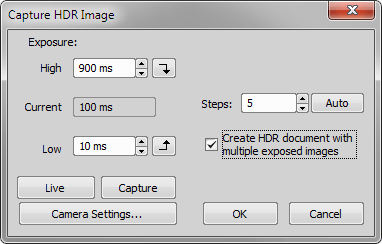
Figure 642.
Set the highest and the lowest exposure values to be included in the capturing. The buttons next to the edit fields enables you to try the exposure times in live image (the buttons set the defined exposure time as current).
the maximum exposure time
indicates the current exposure time on live
the minimum exposure time
Define the number of steps for HDR capturing - how many frames the HDR image will be calculated from. Use the button to calculate optimal number of the steps for the current exposure range.
Applications > HDR > Create HDR from Current ND (requires: High Dynamic Range)
This command creates a HDR image from a ND2 file. The new HDR image opens in a separate window.
Applications > HDR > Create HDR Image from File (requires: High Dynamic Range)
Selects source files for creating an HDR Image. The new HDR image opens in a separate window. If you check the Create Multiexposure Document option, a multichannel image is created.
Applications > HDR > Apply One-Shot HDR to Current Image (requires: High Dynamic Range)
Opens the Apply One-Shot HDR dialog window used for enhancing the dynamic range on the currently opened image.
Use online sign: GMO Sign - this option appears only if on-line signing is available. It allows users to use GMO Sign, a third-party online service. These signed documents are uploaded to the GMO cloud and the user gets an e-mail. More settings to the GMO Sign are done here: Applications > Digital Signing > Setup on-line signing.
Use existing certificate - allows users to select a digital signature already stored on the system. refreshes the list of certificates. Choose one certificate by clicking on it.
Import certificate from file (.pfx / .p12) - manually add new certificates to the system using the button and entering the password. Supported file formats are .pfx and .p12. For sensitive private keys, the system utilizes the Microsoft Platform Crypto Provider (TPM). If TPM is unavailable, it defaults to the Microsoft Software Key Storage Provider.
Generate self-signed certificate (for testing) - this function is explicitly intended for testing purposes. It allows the user to define a Certificate subject name and generate a local certificate without needing an external authority.
API key - this handles authentication with the API.
Mapping (Windows user to API account) - this specifies which Windows user signs via which API account.
Applications > Filter Particle Analysis > Start Application 
(requires: Filters)
This command runs the Filters module. See Filter Particle Analysis for detailed description of all features of the module.
Applications > Digital Signing > Capture Image to PDF (requires: Local Option)
An image is captured directly from the microscope, then saved into a PDF file along with additional metadata and the PDF is immediately signed using the selected certificate.
Optionally enter a Comment text, specify the path where the PDF file will be saved (), and click to select the certificate type (see also Applications > Digital Signing > Select Signing Certificate).
Applications > Digital Signing > Select Signing Certificate (requires: Local Option)
Opens the Select certificate for signing documents dialog window which serves as the interface for choosing how to digitally sign documents within NIS-Elements. The first time a user selects a certificate, it is saved, and the dialog will only open again if manually requested. The dialog displays certificates from the Windows Personal certificate store and should only show certificates that include a private key and are valid for PDF signing.
There are the following methods for managing and applying digital signatures to the report:
Applications > Digital Signing > Setup on-line signing (requires: Local Option)
This dialog sets up the GMO Sign cloud API parameters for online document signing, specifically configuring:
Specify the folder which contains the sequence of images.
Set the dimensions of ND2 file (Time, Z Series, Wavelength, Multipoint). Specify number of dimension frames in the file sequence in the field below.
Select the file which will represent a first frame in ND2 file by double-clicking its name or click on the point before the file name.
Display the focused image.
Select the Edit Area in Focused Image command.* The cursor changes.
Draw an area inside the focused image which should be affected. Finish drawing by right-click.
Use the mouse wheel or arrow keys to browse Z slices within the area.
Finish the procedure by right-click or Enter.
Applications > EDF > Create Focused Image 
(requires: Extended Depth of Focus)
When the method is selected and the sequence is aligned, the only thing to do is to run the Applications > EDF > Create Focused Image command. The focused image will be created and appended to the ND2 file (when the ND2 file is saved to disk the focused image is included).
Z-Map Setting
Sets the method for the Z reconstruction. This reconstruction takes all Z slices and their focused image to create a 3D model of the whole scene called Z-Map. The Balanced method brings more consistent results with less noise and artifacts when compared to the former faster method (Original). If the Z-map calculation is not necessary for your task, select None to speed up the EDF image acquisition.
Applications > EDF > Create Focused Document 
(requires: Extended Depth of Focus)
Creates a new document containing one EDF focused image (Z-stack from the source image is merged into a single frame).
Applications > EDF > EDF Z-Profile 
(requires: Extended Depth of Focus)
Measures within the Z-profile graph. Please see the description of the View > Analysis Controls > EDF Z-Profile  .
.
Applications > EDF > Show Anaglyph 
(requires: Extended Depth of Focus)
This command displays the anaglyph view of the current data-set. The focused image must have been created before. See Extended Depth of Focus.
Applications > EDF > Show Surface View 
(requires: Extended Depth of Focus)
This command displays the surface view of the current data-set. The focused image must have been created before. See Extended Depth of Focus.
Applications > EDF > Open File Sequence (requires: Extended Depth of Focus)
This command opens a sequence of images and creates an ND2 file out of it.
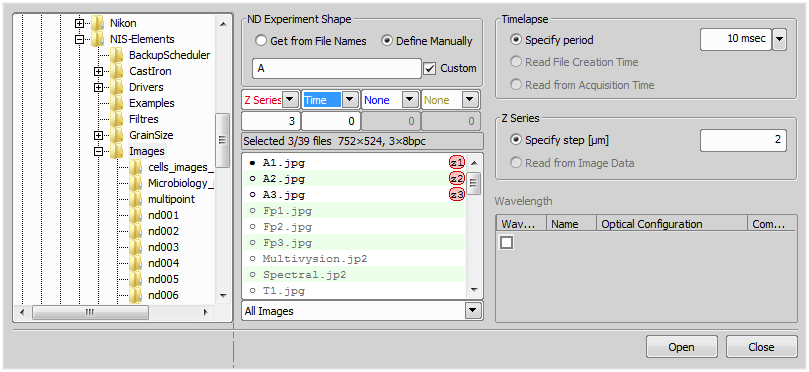
Figure 643.
Dialog options
Mark this button to define ND2 file from file names.
Mark this button if you want to define the files manually.
If you want to edit the name pattern manually, check this item and the text field on the left side of this option becomes editable. Edit the text or enter a new name pattern.
Set Timelapse period value. Specify the exact value from the pull down menu or select to use File Creation Time or Acquisition Time.
(requires: Extended Depth of Focus) (requires: Local Option)
Set the Z Series step as a value (Specify step [µm]) or set the Range (from the First frame to the Last frame) or select to use the Z Series step from image data (Read from Image Data).
Applications > EDF > Align Sequence (requires: Extended Depth of Focus)
This command aligns the current Z series in order for the EDF to work properly.
Applications > EDF > Edit Area in Focused Image (requires: Extended Depth of Focus)
This advanced option enables you to draw an area inside the image and select the Z slice to be used in the resulting focused image.
* - when you have the area defined, the selection can be inverted by pressing G.
Applications > EDF > Edit Background (requires: Extended Depth of Focus)
This function enables the user to handle the background of a Z-series surface image viewed in the Show EDF 3D Surface View ( Applications > EDF > Show Surface View ). After the focused image is created, you can invoke this command. The following dialog appears:
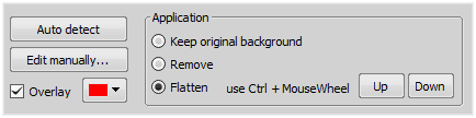
Figure 644.
First, you have to detect the background. Click to perform the auto detection. If the results are not fully satisfying, or in any other case, choose to open the ROI editor. Detect the background using the tools available and then press the Tab key or click  Exit Editor to close the editor.
See Binary Editor.
Check Overlay and set the color of the overlay for better visualization of the edited layer.
Finally choose how to process the background:
Applications > EDF > Show Z-Map Image (requires: Extended Depth of Focus)
This command displays the Z map of an ND document which contains the Z dimension.
Applications > EDF > Real Time EDF 
(requires: Extended Depth of Focus)
The Real Time EDF command is integrating the whole functionality of EDF. It captures a Z-sequence, aligns the images (optionally), and creates the focused image. When the command is invoked, the Real Time EDF dialog appears. Check, whether to align the images or not. See also Real Time EDF.
Applications > EDF > Real Time EDF Manually (requires: Extended Depth of Focus)
The Real Time EDF Manually command is integrating the whole functionality of EDF. It makes the focused image from a Z-sequence captured from the Live stream during manual Z movement. When the command is invoked, the following dialog appears. Check, whether to align the images or create a Z-Map and click .
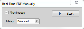
Figure 645.
Applications > Layer Thickness Measurement > Measure Layers (requires: Layer Thickness Measurement) (requires: Local Option)
Opens the Layer Thickness Measurement dialog window.
Applications > Metallography > Cast Iron (requires: Metalo Cast Iron)
This command starts the Metallography - Cast Iron application layout. Please see Metalo - Cast Iron Analysis for further details.
Applications > Metallography > Grain Size (requires: Metalo Grain Size)
This command starts the Metallography - Grain Size application layout. Please see Metalo - Grain Size Analysis for further details.
Applications > Weld Measurement > Measurement Explorer 
(requires: Local Option)
Opens the Measurement Explorer panel.
See also Measurement Explorer.
Applications > Weld Measurement > Measurement Sequencer - Definition 
(requires: Local Option)
Opens the Measurement Sequencer - Definition panel used for the preparation of advanced sequential measurement definitions.
Applications > Weld Measurement > Measurement Sequencer - Run 
(requires: Local Option)
Opens the Measurement Sequencer - Run panel used for executing the measurement definitions previously defined in the Measurement Sequencer - Run window.
Applications > Concrete > Start Concrete 
(requires: Local Option) (requires: Concrete)
Opens the Concrete application (Concrete).