
- Nikon Intensilight
- Nikon C-LEDFI
- Nikon D-LEDI
- Nikon LU4A
- Nikon LUA-S
- Nikon LUD-H
- Nikon LU-N3/4/4S
- Nikon LU-NV
- Nikon LUSU
- Agilent MLC400
- AOTF via NIDAQ - Illumination Device
- CoolLED PrecisExcite
- EXFO X-Cite Exacte
- Sutter Lambda XL
- Lumen Dynamics X-Cite 120
- Lumen Dynamics X-Cite XLED1
- Lumencor LIDA
- Lumencor SOLA
- Lumencor SPECTRA / AURA
- Photonic F3000
- Schott KL 2500 LED
- TILL Photonics Polychrome V
- 89 North Heliophor
Note
The complete list of cameras and devices supported by NIS-Elements is available in a separate document.
This panel manages the Intensilight shutter.
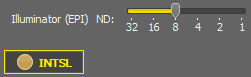
Figure 97.
The shutter can be opened and closed using this  button. The button also indicates the state of the shutter. ND radio slider defines the value of the ND filter.
Caution when using Nikon Intensilight with Nikon Ti2 microscope
When you control Intensilight using the Assist Guide function, it should be connected to Ti2 via the “Remote cable”. In this case the “Remote cable” is used for Ti2 connection and Intensilight remote control pad cannot be used.
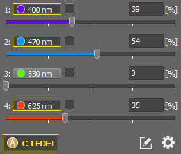
Figure 98.
Both rising and falling edge
Rising edge only
Falling edge only
Turn on/off a desired wavelength(s) by clicking its corresponding button. Adjust its power using the slider or by entering a numeric value into the edit box. All lines which have a check box (next to the line name) selected are automatically synchronized in order to keep the ratio of powers between the lines constant.
C-LEDFI Click this button to turn the selected light modules on/off.
 Customize Pad
 Click on this button to access the laser line customize mode, where you can check the corresponding check box next to each laser line. After exiting the customize mode (by clicking on the button again), only the selected laser lines will be displayed in the control pad.
 Configure
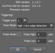
Figure 99.
This button opens the C-LEDFI Configuration window.
Select which Pin Jack connector is used to receive the triggering signal.
Select which edges of the camera TTL signal are used for line switching:
Note
Please select a “high + low edge detection” when you execute Ti-Recipe or Triggered Acquisition using Nikon L3/U3 or Andor Ixon.
Check this box to enable the pulse mode. Instead of emitting continuous light beam, the pulse mode generates light pulses of the defined length.
If this function is turned on, all lines get a check box next to the line name. Power of the selected lines is automatically synchronized in order to keep the power ratio between the lines constant.
Caution when using C-LEDFI with Nikon Ti2 microscope
When you control C-LEDFI by the Nikon Ti2 Microscope from NIS-Elements, then the PC and C-LEDFI should be connected via the USB cable and should be connected from NIS-Elements > Manage Devices > Nikon C-LEDFI.
When you control C-LEDFI using the Assist Guide function, it should be connected to Ti2 via the “Remote cable”. In this case the “Remote cable” is used for Ti2 connection and C-LEDFI remote control pad cannot be used.
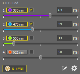
Figure 100.
Turn on/off a desired wavelength(s) by clicking its corresponding button. Adjust its power using the slider or by entering a numeric value into the edit box. All lines which have a check box (next to the line name) selected are automatically synchronized in order to keep the ratio of powers between the lines constant.
D-LEDI Click this button to turn the selected light modules on/off.
Customize Pad Click on this button to access the laser line customize mode, where you can check the corresponding check box next to each laser line. After exiting the customize mode (by clicking on the button again), only the selected laser lines will be displayed in the control pad.
Configure This button opens the configuration window.
Specifies the illuminator connection.
Select the NIDAQ card when connected via NIDAQ.
Depending on the type of NIDAQ card you have, some cards do not support TTL signals. If so, the TTL signal can be simulated through an analog line - select the Analog line option.
A list of lines with their connections to be used as a multi-laser device is displayed here.
Name specifies the name of the control pad, Shutter Delay sets the software delay in milliseconds.
These options select the display mode. Sync mode shows one global laser line which sets all the hidden laser lines to the same intensity whereas Async mode enables the user to tune each laser line separately. Sync mode/Async mode is used for EPI-Fluorescence whereas VIS mode is used for EPI-Brightfield.
If Enable Sync Power is turned on, all lines get a check box next to the line name. Power of the selected lines is automatically synchronized in order to keep the power ratio between the lines constant.
Shows information about the illumination device model and its CPU version. Direct attachment of Nikon D-LEDI to the microscope requires a diffuser. Diffuser (in/out) can be added to the visual device manager as a manual accessory by checking Diffuser Installed. Use IN for the VIS mode and OUT for the Sync mode/Async mode.
The LU4A control panel manages the Nikon LU4 settings:
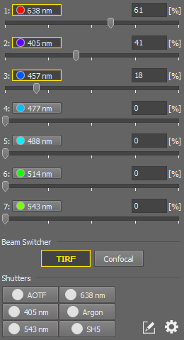
Figure 101.
The number of lines depends on the LU4 settings. Check the check box to activate the corresponding line. You can select more lines at one time. Move the slider to set the corresponding line power in % or enter the exact line power value in the field on the right.
Press the Confocal/ TIRF button to switch between Confocal mode and TIRF mode. In Confocal mode, all controls are disabled except this button.
Here you see all operating shutters selected in the Device Manager. The number of shutters depends on the LU4 settings. Check the shutter item to open the corresponding shutter.
You can select one of the four predefined configurations.
Enter a channel name for the displayed laser wavelength. Only laser lines defined in the laser configurations are available. Check Logarithmic scale to use it for the laser power line.
Check which shutters will be displayed in the main top toolbar.
Define the name which will be shown on the button for the left or right port on the LU4A pad.
The left port of LU-4A is controlled by the connected confocal by default, however, if you prefer to take over the control by other means, you de-select this option.
Displays some useful information about the firmware and SDK.
The LUA-S pad controls the Nikon LUA-S laser device.
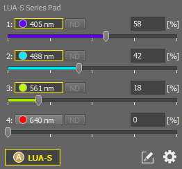
Figure 102. LUA-S Pad
The LUD-H Port pad and the LUD-H Switcher Pad control the Nikon LUD-H device.
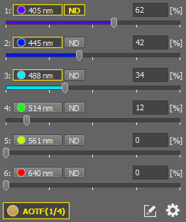
Figure 103. LUD-H Pad
LUD-H Port Pads
The intensity slider bar for each used laser is displayed in a logarithmic scale.
If checked, this function automatically releases the laser beam interlock when it is safe.
LUD-H Switcher Pad
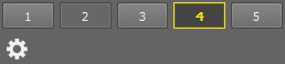
Figure 104. LUD-H Pad
These buttons are used to control the LUD-H output fibers.
Configure Clicking this button opens the LUD-H Configuration window containing the following features:
Automatically detected fibers can be renamed and their adapter can be selected from the combo box.
Contains a list of physical laser lines with information about their wavelength, type and run time. It is also possible to adjust their head power [%].
One of the adapters can have a power exception which then requires a specific time limit to stabilize its power. Checking Block experiment when modulation changes blocks the experiment in cases when user switched to this fiber. Progress bar of the time specified in the combo box is displayed in the LUD-H Switcher window (“wait for stable power”).
If checked, this function automatically releases the laser beam interlock when it is safe.
opens a dialog window where it is possible to select which adapter uses the laser head power exception and adjust its power.
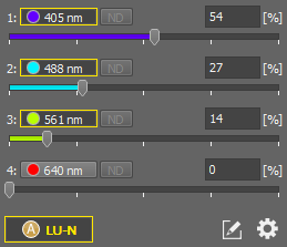
Figure 105.
The LU-N3/4/4S pad controls the particular laser device.
Turn on/off a desired wavelength(s) by clicking its corresponding button. Adjust its power using the slider or by entering a numeric value into the edit box.
LU-N Turns the selected lasers on/off.
Customize Pad Click on this button to access the laser line customize mode, where you can check the corresponding check box next to each laser line. After exiting the customize mode (by clicking on the button again), only the selected laser lines will be displayed in the control pad.
Configure Clicking on this button opens the LU-N GUI Settings with the following options:
The intensity slider bar for each used laser is displayed in a logarithmic scale.
This function automatically releases the laser beam interlock when it is safe.
The LU-NV Pad (Port pad) and the LU-NV Switcher Pad control the Nikon LU-NV device.
Figure 106. LU-NV Pad
LU-NV Port Pads
The intensity slider bar for each used laser is displayed in a logarithmic scale.
If checked, this function automatically releases the laser beam interlock when it is safe.
Figure 107. LU-NV Switcher Pad
LU-NV Switcher Pad
These buttons are used to control the LU-NV output fibers.
Configure Clicking this button opens the LU-NV Configuration window containing the following features:
Automatically detected fibers can be renamed and their adapter can be selected from the combo box.
Contains a list of physical laser lines with information about their wavelength, type and run time. It is also possible to adjust their head power [%].
One of the adapters can have a power exception which then requires a specific time limit to stabilize its power. Checking Block experiment when modulation changes blocks the experiment in cases when user switched to this fiber. Progress bar of the time specified in the combo box is displayed in the LU-NV Switcher window (“wait for stable power”).
If checked, this function automatically releases the laser beam interlock when it is safe.
opens a dialog window where it is possible to select which adapter uses the laser head power exception and adjust its power.
LU-NV Independent Fibers
This pad combines the adjustment and stimulation of the two LU-NV independent fibers. Available options are the same as in LU-NV Port Pads described above.
LU-NV Nidaq Independent Fibers
This pad controls the shutter and power adjustment of the two LU-NV Nidaq Independent Fibers.
LU-NV Nidaq Pad
This pad controls all Nidaq lines in combination with the switcher control (described above in the LU-NV Port Pads section).
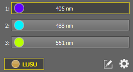
Figure 108.
The AOM LUSU Pad controls the LUSU and AOM devices.
Control Panel Options
Turn on/off a desired wavelength by clicking its corresponding button.
LUSU Switches the selected laser on/off.
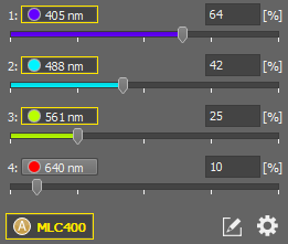
Figure 109.
The MLC Pad controls the Agilent MLC400 laser combiner.
Control Panel Options
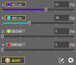
Figure 110.
The AOTF Pad enables the user to control a multi-laser device connected to the system via an NIDAQ card.
Configuration
The following window appears when you press the button.
The device name is used for identification within the system and is displayed on the shutter button.
Analog control controls the power of lines, TTL Control controls the status (on/off). Select the combination you need.
Specifies the connector block connected to your NIDAQ card.
Specify the TTL line signal which activates the line (ON).
Depending on the type of NIDAQ card you have, some cards do not support TTL signals. If so, the TTL signal can be simulated through an analog line - select the Analog line option.
This is the list of lines configured to be used as the multi-laser device.
Specify the number of lines which will be controlled by the NIDAQ card.
Each line contains the following fields:
Name of the line, wavelength of the laser may be used.
Select to which line of the NIDAQ break-out box the corresponding laser is connected.
Select to which line of the NIDAQ break-out box the corresponding laser TTL control is connected.
Specify the voltage range which will be used by the NIDAQ card to control the laser power.
Delay sets a software shutter delay in milliseconds. This delay can be used for example when your camera starts capturing sooner than the other devices waiting for the signal are prepared.
Enable Checkboxes to Hide/Show Laser Sliders adds a checkbox to each laser line.
Segmented Linear Scale option changes the linear scale to non-linear. You can imagine the “segmented linear scale” as a pseudo-logarithmic scale where the distances between values are shorter for higher values.
Slider Values set the units in which the laser power is displayed.
CoolLED PrecisExcite illumination device is controlled through the pE Pad.
Select the active laser line by checking its corresponding radio button. Adjust its power using the slider or by entering a numeric value into the edit box.

Click this button to open/close the shutter of the pE device. This will activate/deactivate the light source.
Click this button to open/close the shutter which activates the connected diascopic illumination.
Device Configuration
You can modify names which are displayed above sliders within the main window. The actual wavelengths read from the device are displayed in the Ex [nm] column.
By selecting this option, two or more wavelengths can be selected at one time.
In case the pE-100 illumination is connected to the controller, select White and specify the name which will be used on the shutter button.
Specify the Name of the shutter which will be displayed on the button in the main window.
Note
The Type pull-down is here for compatibility reasons. Formerly, shutters were identified within the system by Type, but there was only a restricted number of types. In this version, shutters are identified by Name.
Information about firmware version and other details read out from the device controller are displayed in this section.
The Lambda XL Pad enables controlling the Sutter Lambda XL.
The X-Cite120 Pad control panel manages the X-Cite 120 device.The shutter can be opened and closed using this button. The button also indicates the state of the shutter. The ND radio buttons define values of the ND filter. Current value is indicated by the green light control and a bold number.
Control Panel Options
Turn on/off a desired wavelength(s) by clicking its corresponding button. Adjust its power using the slider or by entering a numeric value into the edit box.
The illumination intensity of each module can be set by filling the edit box on the right or by moving the slider.
Switch the selected light modules on/off using this button.
The Lida Pad is used to control the Lumencor LIDA light engine.
Control Panel Options
Turn on/off a desired wavelength(s) by clicking its corresponding button. Adjust its power using the slider or by entering a numeric value into the edit box.
The illumination intensity of each module can be set by filling the edit box on the right or by moving the slider.
Lida The light source can be turned ON / OFF using this button.
The Sola Pad is used to control the Lumencor SOLA light engine.
The Spectra Pad controls the Lumencor SPECTRA/AURA light engine.
Control Panel Options
The F3000 Pad controls the Photonic F3000 LED lightsource.
The Schott KL 2500 LED Pad controls the Schott KL 2500 LED lightsource.
Connecting Polychrome V
Two possible ways of connecting the Polychrome V to PC are available:
Using RS232 interface only
Using RS232 interface + NIDAQ analog output - this type of connection requires a NI card, a Break-Out box from Till Photonics and is necessary to enable Triggered Acquisition
HASP Protection
The NIS-Elements device driver requires two HASP bits included in LW_ MONOCHROMATOR product available as a Local Option on the AHUS site:
Monochromator
Shutter
The Polychrome V Pad controls the TILL Photonics Polychrome V monochromator.
Use the slider or the edit box to select the wavelength [nm] which you intend to use.
(optional)
Use the slider or the edit box to specify the bandwidth range [nm].
(optional)
Use the slider or the edit box to adjust the intensity [nm] of the monochromator.
This button can be used as a shutter to turn the light source on/off.
Shuttering
There are two possible shutter behaviors which can be set in the configuration dialog window:
Triggering
If you want to use the device in Triggered Acquisition, it is necessary to configure the NIDAQ connection in the bottom part of the configuration window.
Note
During Triggered Acquisition only the resting wavelength is used for switching off the light regardless the shuttering settings mentioned above.
Triggered Acquisition requires a wavelength switcher. If only the monochromator is used, it is necessary to connect another device (real device or simulator). We recommend connecting “Nikon C-LEDFI Simulator”. This simulator enables the Triggered Acquisition functionality without occupying any NIDAQ ports or requiring any additional HASP bits.
In triggered acquisition only one power value is used for all defined channels. To be able to use multiple power setups, save each power value together with a new optical configuration ( Calibration > New Optical Configuration
  ).
).
Note
Using of NIDAQ Filter Wheel device in Triggered Acquisition has been improved: if camera readout time is shorter than Filter Wheel speed, the warning message is shown- the Filter Wheel is moved to the correct position on start of Triggered Acquisition- correct metadata (channel color) is provided by this device to the system.
The Heliophor Pad controls the Heliophor light engine.
Control Panel Options
Turn on/off a desired wavelength(s) by clicking its corresponding button. Adjust its power using the slider or by entering a numeric value into the edit box.
The illumination intensity of each module can be set by filling the edit box on the right or by moving the slider.
Switch the selected wavelength modules on/off using this button.