
Having NIS-Elements installed and all hardware accessories set up within the  Devices > Device Manager
  window, you can start capturing images. Let's begin with the simplest case.
Turn the connected camera and other devices ON and start NIS-Elements.
Select a suitable hardware configuration on startup.
Make sure the
 Compact tab is selected with the
  Acquisition
  panel displayed on the right.
Select a lightpath which includes a camera (1).
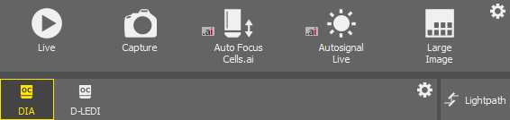
Figure 126.
Display the camera image by the
 Live tool (2).
Adjust Exposure on the camera pad to get a nice image of the scene.
Capture the image by the
Capture tool (4).A new image is opened automatically and named “Captured ...”.

Figure 127. Light path tool bar
Buttons for switching between lightpaths available for the current hardware configuration are displayed below the tool bar of the Acquisition panel. An icon is displayed on each button to indicate the type of lightpath:
 , DIA, EPI
 General acquisition based on optical configurations. Different optical configurations can be created within such a lightpath.
 , DIA, EPI
 General observation lightpath. Different optical configurations can be created within such a lightpath.
 Lightpath
 Click this button to open the Lightpath Scheme  panel which visualizes the current lightpath and may indicate possible errors in the setup.
In case there are some lightpaths you will not use, you can hide them from the tool bar. Click  Configure... or using the
  right mouse button anywhere in the tool bar and select to open the User Visible Buttons window.
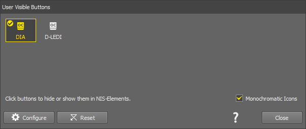
Figure 128.
(De)select any lightpaths you do not want to display. The ones with the tick icon will be displayed in the tool bar.
Optionally change the icon color (color or monochromatic icons).
If you are a user with the privilege Modify devices and light paths, you can even hide some light paths entirely. To do this, use the
Configure button in the same dialog window to open the Button Order and Visibility System Defaults window.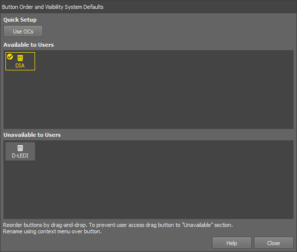
Figure 129.
Drag the buttons to the bottom area to hide them to the users. Change the order of the available buttons by moving the buttons in the Available to Users area. Quick single-click button setups are available in the Quick Setup section in the top of the window. Rename the button in the context menu over the button.
Click to confirm the selection.
Select a lightpath button with the icon . A tool bar with optical configurations appears below the lightpath buttons. The usage of optical configurations (OCs) within the Acquisition panel is the same as in the previous versions of the software where optical configurations were global. The difference is that only OCs created within the currently selected lightpath are displayed here and in the main tool bar of NIS-Elements. Other optical configurations are available only after switching the lightpath.
Note
To change the described default behavior, click right mouse button in the OC tool bar and select Show OCs from all Lightpaths. Moreover, particular OCs can be hidden from the tool bar by the Select Visible Configurations command from the same context menu.
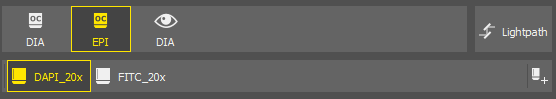
Figure 130.
 Add
Add Click this button to call the Calibration > New Optical Configuration  command.
Sample navigation is integrated into the Compact layout to control mainly the Ji and Ti2 microscope systems. Relying on the geometry of the known Ji/Ti2 microscope holders, this improves the identification of sample location, with added functionality for automatically scanning of slides, wellplates, and dishes. The pad can be undocked (opened as a separate window) using the  button.
Note
Features vary among different software packages and used hardware.
Please refer to Feature dependency on hardware and packages for a detailed comparison of the available functions for each software package and hardware combination.
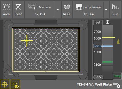
Figure 131. Stage tab
 Area
Area Zooms to the scan area of interest (typically a slide or a coverslip area usable for imaging). This area is highlighted with a yellow rectangle and can be directly adjusted.
 Clear
Clear Overview
 Scans the full sample overview using the settings selected in the drop-down menu. Click on the arrow next to the button and choose Preset or Current Settings. Preset corresponds to the Acquisition Presets defined in the Service Settings ( Devices > Service Settings  ).
).
 ROIs
ROIs This button shows/hides a toolbar with tools used for drawing one or more regions in the preview area which are then scanned using the  button. Description of the specific tools can be found here: Drawing tools. If no region is defined, it is possible to scan just the Area. The newly improved Focus Surface generator is integrated into the built-in job used for the scanning.
 Points
 This button reveals a toolbar with tools used for adding points ( Add) and managing them. Each point is then captured using the Multi-Capture button.
Large Image, Multi-Capture Click the arrow on the right to choose one of the acquisition modes:
Once the button is clicked, further options can be fine-tuned before the Scan/Capture is executed, such as:
Save as
Stitches the large image together creating one large image file.
Does not stitch together, instead a multi-point file is created.
 Run
Run Scans the large image (ROIs or points) using the built-in method.
 Show FOV
 Shows/hides the camera field of view in the preview area.
 Show Area
 Shows/hides the scan area (e.g. a coverslip) in the preview area.
 Select Holder
 Option to choose the relevant holder from the database. Click to select a holder, then refine your selection using the radio button options in the top toolbar. The Holder Alignment Offset at the bottom of the window is used to specify the X and Y offset for the stage alignment. This is necessary when the selected holder is used with a stage requiring an adjustment due to its different range.
If the first holder (Unknown Holder) is selected, the Full Area of the stage is taken into account.
To create a custom holder, click New Custom... and use the drawing tools to draw your custom area. When finished, click Done, name the holder and click .
Context menu over the Preview (similar for all sample holders)
Starts scanning the large image.
Opens the Auto Scale Settings window where the Low and High fields determine how many of all pixels of the picture are left outside the LUTs sliders when Auto LUTs is applied (0-10%). See also Auto Scale Settings.
(requires: Local Option)
Opens the scanned overview or ROI as a new image document.
(requires: Local Option)
If this item is checked, the scanned overview or ROI is automatically opened as a new image document.
Context menu over a Region
Starts scanning the large image inside the selected ROI(s).
Renames/selects/deletes the ROI.
Selects/deselects/deletes all ROIs at once.
Starts scanning the area of interest (white rectangle).
Starts scanning the large image.
Opens the Auto Scale Settings window where the Low and High fields determine how many of all pixels of the picture are left outside the LUTs sliders when Auto LUTs is applied (0-10%). See also Auto Scale Settings.
(requires: Local Option)
Opens the scanned overview or ROI as a new image document.
Z Navigation
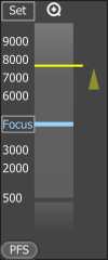
Figure 132. Z Navigation
The vertical column represents the entire Z dimension, with the yellow horizontal line representing the current position, the blue line indicating the Focus position. Place your mouse cursor over the vertical column, then scroll the mouse wheel to adjust the current (yellow) position or double-click a position to move to it.
Sets the current Z position as the “Focus” position. A tool tip over the button shows its Z value.

 Zoom in/out
This button appears only when working with slide samples and resets the focus value to default.
Moves the Z stage to the predefined focus position. A tool tip over the button shows its Z value.
(requires: Local Option)
Turns the perfect focus system (PFS) on and applies the current PFS offset.
There are various combinations of hardware, microscopes, and NIS-Elements packages activating some Sample Navigation features. The following table outlines the different options. Each option is closely described below the table.
Table 3.
| Hardware | Ar package + 6D module + JOBs module | Ar package | Br package | D package |
|---|---|---|---|---|
| Ji/Ti2 microscope, Mono camera supporting fast scan | Option 1 | Option 2 | Option 2 | Option 5 |
| Ji/Ti2 microscope, RGB camera supporting fast scan | Option 3 | Option 5 | Option 5 | Option 5 |
| Ji/Ti2 microscope, Mono/RGB camera not supporting fast scan | Option 4 | Option 6 | Option 6 | Option 6 |
| Ni-E/other microscope + MZH+Aux, Mono/RGB camera supporting fast scan | Option 3 | Option 5 | Option 5 | Option 5 |
| Ni-E/other microscope + MZH+Aux, Mono/RGB camera not supporting fast scan | Option 4 | Option 6 | Option 6 | Option 6 |
| Ni-E/other microscope, Mono/RGB camera | Option 4 | Option 6 | Option 6 | Option 6 |
See Cameras supported for continuous movement.
Important
Service Settings dialog is available only:
in Ar and Br packages.
for Ji and Ti2 microscopes.
for Mono cameras from the fast scanning supported list (see Cameras supported for continuous movement).
Fast scanning is supported:
on selected cameras (Mono or RGB) only (see Cameras supported for continuous movement).
on selected XY Stages (Ji, Ti2, MZH+Aux).
Fast scan can always switch to the step-by-step mode if the application determines that it will be faster.
List of Options:
Built-in Job
Custom Job
Generate Focus Surface
Current Z-Level
Create Large Image
Store Single Images
Current Settings
Optical Configuration
Service Settings
Sample swap
Current Z
Current Settings
Optical Configuration
Service Settings
Generate Focus Surface
Current Z-Level
Create Large Image
Store Single Images
Current Settings
Optical Configuration
Service Settings
Sample swap
Current Z
Current Settings
Optical Configuration
Service Settings
Built-in Job
Custom Job
Generate Focus Surface
Current Z-Level
Create Large Image
Store Single Images
Current Settings
Optical Configuration
Sample swap
Current Z
Current Settings
Optical Configuration
Built-in Job
Custom Job
Generate Focus Surface
Current Z-Level
Create Large Image
Store Single Images
Current Settings
Optical Configuration
Current Z
Current Settings
Optical Configuration
Generate Focus Surface
Current Z-Level
Create Large Image
Store Single Images
Current Settings
Optical Configuration
Current Z
Current Settings
Optical Configuration
Generate Focus Surface
Current Z-Level
Create Large Image
Store Single Images
Current Settings
Optical Configuration
Current Z
Current Settings
Optical Configuration
Scanning is performed by the continuous movement (fast). “Large Image” can be scanned by a custom or a built-in job (scanning routine).
Available features for option1 :
 Full mode) Full mode) Area mode)
 Scanning is performed by the continuous movement (fast). “Large Image” can be scanned by the built-in job (scanning routine) only.
Available features for option 2:
Full mode) Full mode) Area mode) Scanning is performed by the continuous movement (fast). “Large Image” can be scanned by custom or build-in job (scanning routine). Service settings are not available for this configuration.
Available features for option 3:
Full mode) Full mode) Area mode) Scanning is performed by the step-by-step movement (slower). “Large Image” can be scanned by the custom or built-in job (scanning routine). Service settings are not available for this configuration.
Available features for option 4:
Full mode) Full mode) Area mode) Scanning is performed by the continuous movement (fast). “Large Image” can be scanned by the built-in job (scanning routine) only. Service settings are not available for this configuration.
Available features for option 5:
Full mode) Full mode) Area mode) Scanning is performed by the step-by-step movement (slower). “Large Image” can be scanned by the built-in job (scanning routine) only. Service settings are not available for this configuration.
Available features for option 6:
Full mode) Full mode) Area mode) The Devices > Service Settings window allows adjustments to the microscope and camera settings which are applied to the well plate overview scanning. Settings adjusted here also influence the acquisition controls in the Acquisition panel.
Note
Sufficient user rights are required for this function to be accessible.
Depending on the microscope model, some of the options could not be available.
Nikon Ni-E
Nikon Ni-E service settings are integrated into one dialog window.
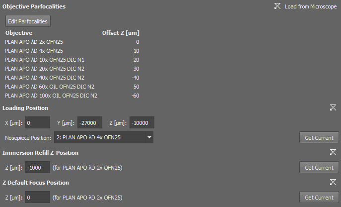
Figure 133. Service Settings for the Nikon Ni-E.
Select an objective on the microscope pad.
Precisely focus on the sample.
Click .
Repeat the previous steps for all mounted objectives.
Click to save the parfocalities.
 Load From Microscope
 Resets all the values to default as they are set in the microscope.
Click to enter the edit mode used for setting the Z-position offsets between the objectives.
(requires: Local Option)
Sets the stage X, Y and Z coordinates of the Loading Position (position for loading the samples). Loading position can be linked with a selected objective (Nosepiece Position) or the current objective can be used (Keep Current Objective). To fill in the current position click . To reset the settings to default, click .
(requires: Local Option)
Defines the Z-coordinate position used when refilling the immersion medium. To fill in the current position click . To reset the settings to default, click .
(requires: Local Option)
Specifies the default focus position in the Z dimension. To fill in the current position click . To reset the settings to default, click .
Closes the dialog window.