
(requires: Automatic Measurement)
The following list contains all features which can be measured within NIS-Elements Measurements. There are the following. Different measurement tools measure different features. If not stated otherwise, all distances and areas are measured in the current (image) calibration units. If the image is not calibrated, pixels are used instead.
Regardless of measurement type.
AcqTime , Angle , Area , Axis A , Axis A/B, Axis B, BinaryArea , BinaryAreaFraction , Blue , BoundsAbsBottom , BoundsAbsLeft , BoundsAbsRight , BoundsAbsTop , BoundsBottom , BoundsLeft , BoundsPxBottom , BoundsPxLeft , BoundsPxRight , BoundsPxTop , BoundsRight , BoundsTop , BrightVariation , CentreX , CentreXabs , CentreXpx , CentreY , CentreYabs , CentreYpx , Channel , Circularity , Comment , Convexity , DensityVariation , Diameter , Edf Ra , Edf Rz , Edf_Sa, Edf_Sz, EdfRoughness , EdfSurface , Elongation , EqDiameter , FieldID , FillArea , FillRatio , Green , Height , HueTypical , HueVariation , IntensityVariation , Length , Length xy, Length xyz , LineLength , MaxFeret , MaxFeret90, MaxIntensity , Mean*ChannelName* , MeanBlue , MeanBrightness , MeanCa2+ , MeanChord , MeanCorrFRET, MeanDensity , MeanFRETEff, MeanGreen , MeanIntensity , MeanRatio , MeanRed , MeanSaturation , MeanTitration , MeasuredArea , MinDistanceTo , MinFeret , MinIntensity , ND.M, ND.T, NearestObjDist , NumberObjects , NumberObjectsRestricted , Numbers , Obj ID , ObjectAreaFraction , Orientation , OuterPerimeter , Perimeter , PerimeterContour , Radius , Red , Roi ID , ROIArea , Roughness , RoughnessInf , ShapeFactor , Source , StartX, StartXpx, StartY, StartYpx, StgPosX, StgPosY, Sum*ChannelName* , SumBrightness , SumDensity , SumIntensity , SurfVolumeRatio , Time , Velocity , VolumeEqCylinder , VolumeEqSphere , Width
- available in manual measurement.
Angle , Area , Axis A , Axis A/B, Axis B, Blue , CentreX , CentreY , Channel , Comment , Diameter , Edf Ra , Edf Rz , Edf_Sa, Edf_Sz, EdfRoughness , EdfSurface , EqDiameter , Green , Height , Length , Length xy, Length xyz , MaxFeret , MaxFeret90, MaxIntensity , MeanBrightness , MeanDensity , MeanIntensity , MinFeret , MinIntensity , ND.M, ND.T, Numbers , Perimeter , Radius , Red , Roughness , ShapeFactor , Source , SumBrightness , SumDensity , SumIntensity , Time , Velocity
- measured under binary objects (layers).
AcqTime , Area , BoundsAbsBottom , BoundsAbsLeft , BoundsAbsRight , BoundsAbsTop , BoundsBottom , BoundsLeft , BoundsPxBottom , BoundsPxLeft , BoundsPxRight , BoundsPxTop , BoundsRight , BoundsTop , BrightVariation , CentreX , CentreXabs , CentreXpx , CentreY , CentreYabs , CentreYpx , Channel , Circularity , Comment , Convexity , DensityVariation , Edf_Sa, Edf_Sz, EdfRoughness , EdfSurface , Elongation , EqDiameter , FieldID , FillArea , FillRatio , HueTypical , HueVariation , IntensityVariation , Length , LineLength , MaxFeret , MaxFeret90, MaxIntensity , Mean*ChannelName* , MeanBlue , MeanBrightness , MeanCa2+ , MeanChord , MeanCorrFRET, MeanDensity , MeanFRETEff, MeanGreen , MeanIntensity , MeanRatio , MeanRed , MeanSaturation , MeanTitration , MeasuredArea , MinDistanceTo , MinFeret , MinIntensity , NearestObjDist , Obj ID , Orientation , OuterPerimeter , Perimeter , PerimeterContour , Roi ID , Roughness , RoughnessInf , ShapeFactor , Source , StartX, StartXpx, StartY, StartYpx, Sum*ChannelName* , SumBrightness , SumDensity , SumIntensity , VolumeEqCylinder , VolumeEqSphere , Width
- measured over the whole image area.
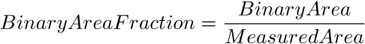
AcqTime , BinaryArea , BinaryAreaFraction , BrightVariation , CentreX , CentreXabs , CentreXpx , CentreY , CentreYabs , CentreYpx , Channel , Comment , DensityVariation , Edf_Sa, Edf_Sz, EdfRoughness , EdfSurface , FieldID , HueTypical , HueVariation , IntensityVariation , MaxIntensity , Mean*ChannelName* , MeanBlue , MeanBrightness , MeanCa2+ , MeanChord , MeanCorrFRET, MeanDensity , MeanFRETEff, MeanGreen , MeanIntensity , MeanRatio , MeanRed , MeanSaturation , MeanTitration , MeasuredArea , MinIntensity , ND.M, ND.T, NumberObjects , NumberObjectsRestricted , Perimeter , Source , StgPosX, StgPosY, Sum*ChannelName* , SumDensity , SumIntensity , SurfVolumeRatio
- measured within ROIs.
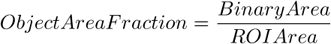
AcqTime , BrightVariation , CentreX , CentreXabs , CentreXpx , CentreY , CentreYabs , CentreYpx , Channel , Comment , DensityVariation , Edf_Sa, Edf_Sz, EdfRoughness , EdfSurface , FieldID , HueTypical , HueVariation , IntensityVariation , MaxIntensity , Mean*ChannelName* , MeanBlue , MeanBrightness , MeanCa2+ , MeanChord , MeanCorrFRET, MeanDensity , MeanFRETEff, MeanGreen , MeanIntensity , MeanRatio , MeanRed , MeanSaturation , MeanTitration , MeasuredArea , MinIntensity , ND.M, ND.T, NumberObjects , ObjectAreaFraction , Perimeter , Roi ID , ROIArea , Source , StgPosX, StgPosY, Sum*ChannelName* , SumBrightness , SumDensity , SumIntensity , SurfVolumeRatio
- can be measured only after EDF focused Image was created.
Edf Ra , Edf Rz , Edf_Sa, Edf_Sz, EdfRoughness , EdfSurface
Open a timelapse ND2 file and run
 View > Image > ND View > Slices View
  .
.Right-click one of the side views and select Create New Document from this View. A new image will be created.
Perform length measurement on the new image.
Acquisition time of the current image in seconds. If the image is a part of an image sequence, the time is measured from the beginning of the sequence. Otherwise it is the time elapsed since the software was started.
Arithmetic mean of pixel intensities of the blue component within the measured area. See Measurement Tools. It equals 0 on other than RGB images.
These are distances (X/Y coordinates) of the left, right, top, and bottom edges of the object bounding rectangle.
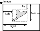
Figure 221. Bounds
These are absolute distances (X/Y coordinates) of the left, right, top, and bottom edges of the object bounding rectangle within a motorized stage range. This feature can be measured only if a motorized stage is connected.
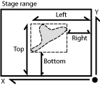
Figure 222. BoundsAbs
These are distances (X/Y coordinates) of the left, right, top, and bottom edges of the object bounding rectangle measured in pixels.
Absolute coordinates of the center of gravity in the scope of the stage XY range. These features can be measured only when a motorized stage is connected. See also BoundsAbsLeft .
Circularity of a circle equals 1. All other shapes are characterized by circularity smaller than 1. It is a derived shape measure, calculated from Area and Perimeter . It is useful for examining shape characteristics.
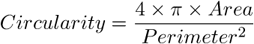
Figure 223.
Indicates convexity of the object edges.
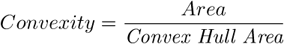
Figure 224.
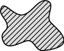
“Convex Hull Area” is the area of objects after running the Binary > Convex Hull command.
See also Area .
Arithmetical mean height of the EDF profile specified by the  Length 3D tool. It is an arithmetical mean of absolute values of differences between 10 Z values along the profile and their mean. Its value for a flat profile is 0.
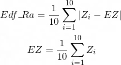
Figure 225.
EDFSurface Z coordinate measured at 10 equidistant points on the profile line.
Mean height of the 10 points on the Z-profile.
Maximum height of the EDF profile specified by the Length 3D tool. Difference between the maximal and the minimal height within the measured profile line.
Arithmetical mean height. Based on the 3D EDF surface model, it indicates how much the surface is rough. It is a sum of absolute values of differences between Z value of each pixel and mean of all Z values divided by Area . Its value for a flat surface is 0. It is the most widely used one-dimensional roughness parameter.
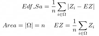
Figure 226.
EDFSurface Z coordinate of a particular pixel.
The mean height of the Z-map (mean of all Z coordinates of the EDFSurface).
Number of pixels in the measured area (image/object/ROI).
Maximum height of the EDF surface. Difference between the maximal and the minimal height within the measured area.
Based on the 3D surface model, it is an approximation of the surface area. For a flat surface, EdfSurface = Area .
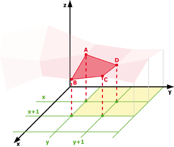
Figure 227. EdfSurface highlighted red, Area of four Edf surfaces highlighted yellow
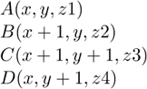
Figure 228.

Figure 229.
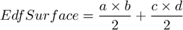
Figure 230.
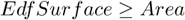
Figure 231.
Based on the 3D EDF surface model, it indicates how much the surface is rough. Its value for a flat surface is 1.
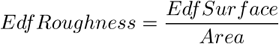
Figure 232.
See also EdfSurface and Area .
A size feature derived from the area. It determines the diameter of a circle with the same area as the measured object:
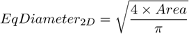
Figure 234.
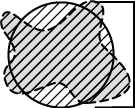
Figure 235. EqDiameter
If an object contains holes, FillArea remains the same while Area is reduced by the area of the holes. If an object does not contain holes, then FillArea = Area .
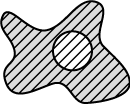
Figure 236. FillArea
The ratio of Area and FillArea :
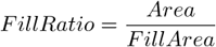
Figure 237.
If an object does not contain holes, FillRatio = 1. If an object contains holes, FillRatio is less than 1. This feature helps distinguish objects with and without holes.
IntensityVariation is derived from the intensity histogram. It is an usual standard deviation of intensity values. This feature describes the inner structure of an object or a field.
Arithmetic mean of pixel intensities of the Green component within the measured area. See Measurement Tools. It equals 0 on non-RGB images.
HueTypical (H) is the hue value with maximum frequency in the hue-values histogram. This feature describes the most frequent hue (color) in an object or field.
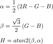
Figure 238.
HueVariation is the usual standard deviation of hue values. This feature describes hue (color) distribution of inner structure of an object or a field.
Figure 239.
Length is a derived feature appropriate for elongated or thin structures. Since it is based on the rod model, it is useful for calculating length of medial axis of thin rods.
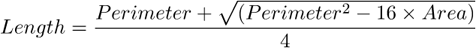
Figure 240.
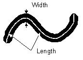
Figure 241. Length
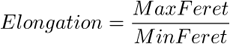
It is the maximal value of the set of Feret's diameters. Generally (for convex objects), Feret's diameter at angle α equals the projected length of the object at angle α , α (0,180); NIS-Elements calculates Feret's diameters for α =0, 10, 20, 30, ..., 180.
The MaxFeret90 is a length projected across the MaxFeret diameter.
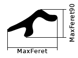
Figure 242. MaxFeret
It is derived from the intensity histogram as the maximal of all pixel intensity values (I).
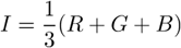
Figure 243. Intensity
It is derived p from the intensity histogram as the arithmetic mean of pixel intensities (I).
Figure 245. Intensity
Arithmetic mean of pixel intensities of one image component. See also MeanIntensity .
The mean value of secants in the 0, 45, 90 and 135 degrees directions. It is a derived feature and is calculated from the Area and mean projection according to the following formula.
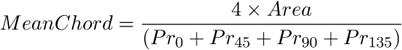
Figure 246.
Arithmetic mean of saturation values of pixels (S).
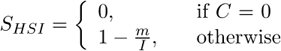
Figure 247. Saturation
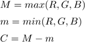
Figure 248.
Arithmetic mean of intensities of the Ratio, Ca2+, FRET / Corr FRET / FRET Eff / Ph channels. This feature is activated upon creation of the channel view.
The area of the measurement frame or a ROI within the measurement frame (if the ROI is on).
The minimal value of the set of Feret's diameters. Generally (for convex objects), Feret's diameter at angle α equals the projected length of object at angle α , α (0,180); NIS-Elements calculates Feret's diameter for α =0,10,20, 30, ..., 180.
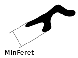
Figure 249. MinFeret
Its value is derived from the intensity histogram. It is the minimum of intensity values of pixels.
Figure 250. Calculation of Intensity (I)
The number of objects inside the measured area. Exclusion rules for counting objects are taken into account (see Measurement Options).
Number of objects left after applying restrictions.
See also View > Analysis Controls > Restrictions  .
.
The angle at which MaxFeret is measured. Feret's diameters are calculated with 5 degrees angle increment.
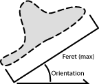
Figure 251. Orientation
Length of the outer perimeter (unlike in Perimeter , holes inside the object do not count).
The total boundary length. It includes both the outer and inner boundaries (if there are holes inside an object). The perimeter is calculated from four projections in the directions 0, 45, 90 and 135 degrees using Crofton's formula
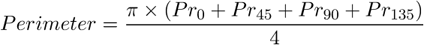
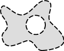
Figure 252. Perimeter
Total boundary length computed from object contours. Compared to Perimeter , it is more accurate (especially on elongated objects) but the calculation is slower.
Arithmetic mean of pixel intensities of the Red component within the measured area. See Measurement Tools. It equals 0 on non-RGB images.
This feature indicates how much the object is rough. “1” means the object roughness is minimal (it is circular). The range is <0;1>.
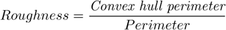
Figure 253.
This feature indicates how much the object is rough. “1” means the object roughness is minimal (it is circular). The range is <1;inf>.
Figure 254.
This feature indicates whether the object is rough or not.
Figure 255.
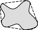
Figure 256. ShapeFactor
When you scan the image from the origin in left-to-right direction, the first pixel of the object you hit is the one with StartX and StartY coordinates.
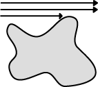
Figure 257. StartX, StartY
Coordinates of the absolute position of the measured field. It is available only for systems equipped with a motorized XY stage.
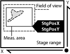
Figure 258. StgPos
A sum of individual optical densities (O.D.) of pixels in the measured area. This feature describes, for instance, the amount of a substance in biological sections. Optical density is evaluated according to the following formula:
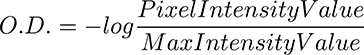
Figure 259.
SurfVolumeRatio is a feature with a strong stereological interpretation: if you measure on fields that are sampled systematically and independently of the content of the sections, then the feature is an unbiased estimator of the surface area of objects (inner structure) per volume of the whole sample.
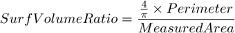
Figure 260.
See also Perimeter and MeasuredArea .
This parameter is based on the rod model. Length is interpreted as height and Width is interpreted as the base diameter of a cylinder.
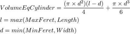
Figure 261.
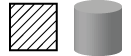
Figure 262. VolumeEqCylinder
Volume of a sphere whose diameter is equal to EqDiameter of the measured 2D object.
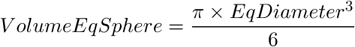
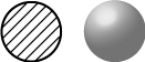
Figure 263. VolumeEqSphere
Width is a derived feature appropriate for elongated or thin structures. It is based on the rod model and is calculated according to the following formula:
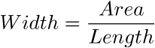
Figure 264.
Figure 265. Width
Speed measured between two points defined manually. This feature can be measured on a 1DT image using length measurement tools. 1DT image can be created from a timelapse ND file.
Lengths of the major (A) and minor (B) axes of an ellipse and their ratio. See Measurement Tools.
3D length measured manually. Length xyz is the actual length measured on Slices View or Volume View. Length xy is length of a projection of the measured line to the XY plane. See Measurement Tools.