
If you want to perform measurements on captured images it is needed to calibrate the objective used to capture images. Whenever an image is captured through a calibrated objective, the image inherits its calibration.
Run the  Calibration > Objectives command. The Objectives window appears:
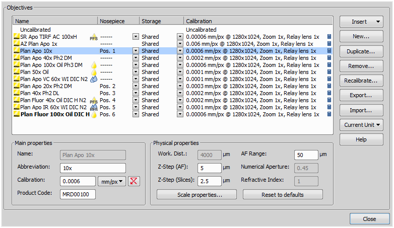
Figure 50.
A list of used objectives can be created within the Objectives window. For each objective, the objective name, position in the changer, storage status and the calibration are displayed. A Calculator  icon next to the calibration value indicates that the calibration has been calculated from objective properties. If the calculator icon is missing, the calibration has been performed manually. Use the buttons on the right side to manage the objectives. Edit the properties of the selected objective in the bottom part of the window.
Display the microscope control pad -
View > Acquisition Controls > Microscope Pad 
A window appears which enables you to select one of the available objectives to the corresponding position.
Each objective has its specifications displayed in the table. These specifications are not editable.
 button in the
 Icons by the objective names indicate the objective type. The following combinations are available:
Dry.

Water immersion.

Oil immersion.

Silicone oil immersion.

PFS.

PFS with support for glass/plastic dish.

Water immersion dispenser (WID).
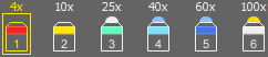
Figure 51. Mounted objectives with tips indicating the immersion medium.
Once such objective is mounted, the tip of the objective icon in the nosepiece section indicates its immersion medium with a color relevant to the mentioned symbols:
no color = air
blue = water immersion
yellow = oil immersion
white = silicone immersion
After you press the Recalibrate button in the Objectives window or when creating a new custom objective, the following window appears:
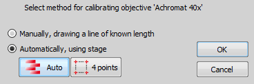
Figure 52.
Select one of the calibration methods:
The Manual calibration lets you draw a distance into a picture and assign real length to it. The live image starts automatically and a window appears. Proceed to: Manual Calibration
If a motorized XY stage is available, the Auto and 4 points buttons appear. Proceed to: Objective Calibration Using XY stage.
Press to continue.
Superresolution Calibration
This type of calibration is available after successful manual or automatic calibration. It triples the camera's resolution and uses fine stage movements to improve the resulting objective calibration. Click the button and wait till the objective is calibrated.
Manual calibration requires the user to specify a distance in the image. It can be either a measurable distance or the size of one pixel. The following procedure can be used for different purposes:
Calibrating of an image (see Calibration)
(Re)calibrating of an objective (see Objective Calibration)
(Re)calibrating of a microscope zoom (see Nikon AZ100 Microscope)
The following window appears:
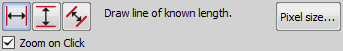
Figure 53.
If you know the size of one pixel, click the button.
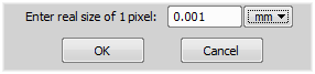
Figure 54.
Enter the value and finish the calibration by the button.
If you do not know the pixel size, you will need to specify distance in the image. For this purpose, use an image of a calibration slide or a ruler captured with your current system configuration.
The distance is defined by placing lines to the image. If you are sure the calibration pattern is perpendicular to image edges, it is recommended to select either vertical
 or horizontal
  lines. Otherwise, select the parallel lines
  .
.Click into the image to place the first line and then the second line to specify the distance:
, You can modify the line position while holding the primary mouse button. After you release the button no further changes can be made. Place the second line in the intended position by another click.
Draw the first line by clicking twice inside the image. The line can be moved and adjusted arbitrary by mouse. When satisfied, finish the first line by right-click. The second line can be placed by another click to the image, this time only to adjust the distance from the first line. The process is completed by right-click.
Zoom on Click zooms the image after the mouse button is clicked so that the position of the point can be set precisely.
Then the following dialog box appears:
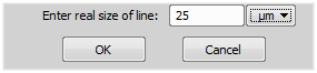
Figure 55.
Enter the distance between the two lines and select correct units.
Click to finish the calibration.
This procedure requires a motorized stage. Select one of the following methods:
Move the stage to another area of the specimen to get a better texture.
Improve contrast by setting LUTs.
Check focus, re-focus if needed.
Turn on the shading correction (see Shading Correction).
The Auto method is fully automatic. Calibration is performed on a part of the live image marked by red square that is shown before the calibration is launched. You can also choose the channel to be used by auto-calibration.
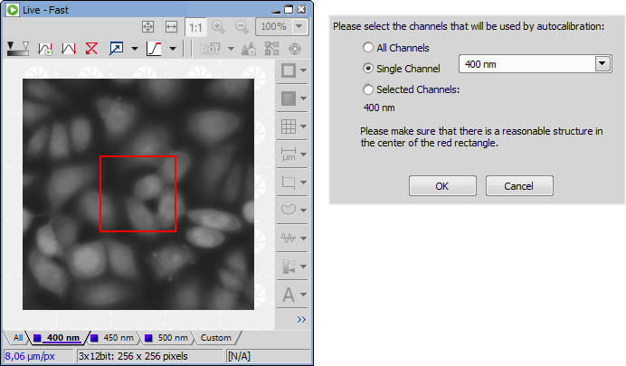
Figure 56. Auto-calibration window
NIS-Elements moves the motorized stage, acquires two images, and calculates the calibration from the shift of the images. The auto-calibration performs an estimation of the real relay lens zoom factor. If the estimation does not match the value specified in the Device Manager window, a warning appears.
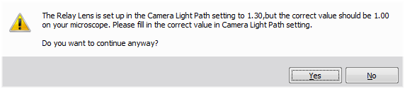
Figure 57. Example of the warning message
It is recommended to cancel the auto calibration (click ), check the real zoom factor of your relay lens and set correct relay lens settings in the Device Manager.
Note
The success of this method depends on the texture of the specimen, its contrast, illumination, etc. If the combination of these factors is unsuitable, the auto calibration may fail. If it fails, try the following:
A real zoom factor can be displayed within the image window. In order for the value to be accurate, both the image calibration and the monitor calibration must be accurate. To calibrate the monitor:
Display a context menu over a calibrated image and select the
 Show Physical Zoom command. The computed value appears in the top left corner of the image. If the current image is not calibrated, the box will show N/A.
Right-click the box with the zoom value and select Monitor Calibration, the following window appears.
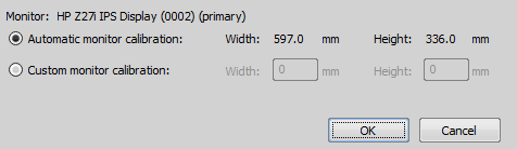
Figure 58. Monitor Calibration Dialog
Caution
The dialog displays calibration of the monitor on which it is displayed. If you have multiple monitors, move the dialog between them.
Check the Width and Height values and whether they match the real size of your monitor.
If you are not sure whether the detected calibration is correct, select Custom monitor calibration. Take a ruler or a measuring tape and measure width and height of your monitor. Enter these values and confirm the calibration by the button.
Create an INI file containing specification of the new objectives (see the example INI below).
Copy the INI file to NIS-Elements installation folder (where the executable file is placed).
Start NIS-Elements. The objectives are loaded to the database automatically.
Example INI file: objectives.ini