- Nikon Ci-E Microscope
- Nikon AZ100 Microscope
- Nikon Eclipse LV Series Microscope
- Nikon Eclipse L200N(D)/L300N(D) Microscope
- Nikon Eclipse MA200 Microscope
- Nikon MM 400/800 Microscopes
- Nikon Ni-E Microscope
- Nikon Ni-U/Ni-L Microscope
- Nikon SMZ Stereomicroscopes
- Nikon Ti2-E Microscope
- Nikon Ti2-A Microscope
- Nikon Ti2-U Microscope
Note
The complete list of cameras and devices supported by NIS-Elements is available in a separate document.
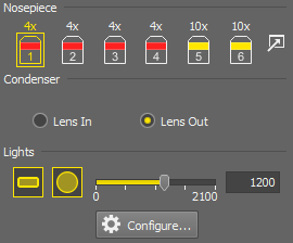
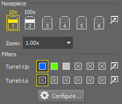
Figure 76.
The CI-E Pad (fully armed) consists of the following portions:
The motorized objective changer can be controlled via this portion of the window. If a move from position 1 to position 5 is ordered a warning appears. This behavior shall prevent high magnification objectives from striking the XY stage.
Use the  button to select objectives from the database of objectives. Please see Assigning Objectives to Nosepiece Positions where also the objective icons and color symbols are described.
You can insert or remove the condenser lens by these two radio buttons.
Note
Condensor setting (In/Out) can be bound to nosepiece positions when using the hardware remote control. In NIS-Elements, use optical configurations to achieve the same behavior (see Optical Configurations)
The microscope LED illumination can be controlled from here.
 Configure
 A window with detailed information about the software opens when you press this button.
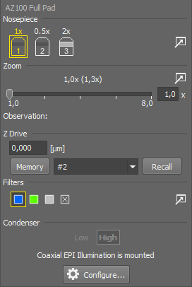
Figure 77.
Note
You cannot use the handheld remote controller and foot switch while the MULTIZOOM AZ100M is connected to NIS-Elements.
The AZ100 Microscope Control Pad consists of the following portions:
Enter the exact position of the Z-drive. The range is <-80,0>
The current position can be memorized by pressing the Memory button. The position value will be remembered under the currently selected position.
To move the Z drive to a memorized position, select the desired value from the pull-down menu and press the Recall button.
This pad indicates the nosepiece status: the currently selected objective and objectives magnification. The objective changer can not be controlled by NIS-Elements.
Use the button to select objectives from the database of objectives. Please see Assigning Objectives to Nosepiece Positions where also the objective icons and color symbols are described.
Zoom magnification can be changed by moving the slider. The current zoom factor is indicated above. The user can calibrate the zoom manually via the button on the right. See AZ100 Zoom Calibration
Note
Since the zoom device is a part of the microscope equipment, concerning optical configurations, its settings are automatically treated as an inseparable part of microscope settings (there is no Zoom in the Used devices box).
The Z drive can be controlled via the microscope control pad in the following way:
The currently selected filter of the four available filter positions is indicated in this portion of the pad. The filter changer cannot be controlled by NIS-Elements. Filters assignment may be changed after pressing the button.
These buttons indicate the current condenser lenses position. The condenser cannot be controlled.
The default calibration of the microscope zoom can modified by the following procedure:
Run live camera image and place a calibration sample to the field of view (e.g. a ruler).
Click the
button in the Zoom section of the microscope pad. A dialog window appears.Change Zoom to the value you are about to correct/calibrate by the slider and click the button.
Calibrate the live image manually. See also: Calibration.
A new Corrected value is added to the Corrected Zoom Values table.
Repeat this procedure for different zoom factors. The resulting calibration is a linear approximation of all the values in the table.
Dialog Options
Changes zoom on the microscope.
Starts manual calibration for the current zoom. See also Calibration.
Resets the calibration table to default values.
The calibration table can be saved to a XML file and loaded later. Use these buttons and standard Open and Save dialog windows.
Motorized devices achieve better positioning repeatability if a backlash compensation is used. The software backlash compensation ensures that the movement direction used to reach a certain position (of a zoom or a nosepiece) is always the same. For example, if you change zoom from 1x to 2x, the movement is direct, but if you change from 3x to 2x, the zoom changes to 1x first and than to 2x in order to reach the position from the same direction.
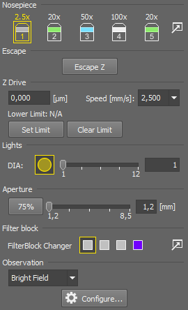
Figure 78.
The LV (fully armed) Microscope Control Pad consists of the following portions:
Displays the mounted objectives.
The motorized objective changer can be controlled via this portion of the window. If a move from position 1 to position 5 is ordered a warning appears. This behavior shall prevent high magnification objectives from striking the XY stage.
Caution
This behavior is valid if the Limit Control option is turned off in LV Setup. If Limit Control is turned on, the warning appears if a move is ordered from a lens with magnification 5x (or less) to a lens with Working Distance less then 1 mm.
Use the button to select objectives from the database of objectives. Please see Assigning Objectives to Nosepiece Positions where also the objective icons and color symbols are described.
Press this button to move the Z drive to the position most away from the sample. Use it when changing objectives or slides on the XY stage or during XY stage initialization. When the button is de-selected, the Z drive moves back to the most recent position.
The current Z position is displayed in the edit box. A particular value can be inserted as well and confirmed by pressing Enter to move the Z-drive.
Intensity of episcopic and diascopic illumination sources can be controlled from here. LED illuminators are also supported.
75% sets the aperture stop to 75% of the objective pupil. The slider with the edit box set a custom aperture size.
Controls the connected shutter.
There are 4 available positions in the changer. The first two have fixed filters for bright field (BF) and dark field (DF) microscopy. The other two are available for any filters.
Use the button to select the filters from the database of filters.
Defines the observation mode.
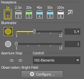
Figure 79.
The L200/L300 Microscope Control Pad consists of the following portions:
The motorized objective changer can be controlled via this portion of the window. If a move from position 1 to position 5 is ordered a warning appears. This behavior shall prevent high magnification objectives from striking the XY stage.
Use the button to select objectives from the database of objectives. Please see Assigning Objectives to Nosepiece Positions where also the objective icons and color symbols are described.
A halogen lamp or the Nikon Intensilight illumination device can be attached to the EPI port of the microscope. Both illuminators can be controlled from here (see below). If two halogen lamps are attached, the illumination control works as the EPI/DIA switcher.
These two arrows control the EPI aperture stop equally to the buttons on the microscope body.
Note
It is not possible to save the aperture status to an optical configuration. The only way to adjust it is by these two buttons (or the buttons on the body).
You can select from where the lamps will be controlled:
from the Control Pad
from the microscope body
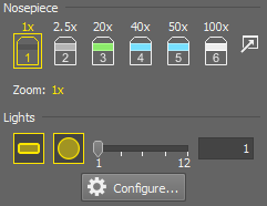
Figure 80.
The MA200 Inverted Metallurgical Microscope Control Pad consists of the following portions:
The motorized objective changer can be controlled via this portion of the window. If a move from position 1 to position 5 is ordered a warning appears. This behavior shall prevent high magnification objectives from striking the XY stage.
Indicates the current state of the MA Zoom device. There are three predefined magnifications (1x, 1,5x, 2x).
A halogen lamp or the Nikon Intensilight illumination device can be attached to the microscope and controlled from here. If the halogen lamp is attached to the microscope, internal (manual) or external (via NIS-Elements) control can be selected on the back of the microscope body. LED illuminators are also supported.
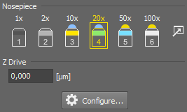
Figure 81.
This measuring microscope connected to NIS-Elements provides two logical devices:
Displays the mounted objectives.
Two types of nosepiece can be attached to the microscope, manual or intelligent.
See Motorized, Intelligent and Manual Devices.
After adding the MM microscope to the system via Device Manager, the Nosepiece logical device becomes available. Display its control panel by the  View > Acquisition Controls > Nosepiece
  command. The type of the nosepiece must by defined via the hardware control pad in order to be recognized by NIS-Elements.
Use the button to select objectives from the database of objectives. Please see Assigning Objectives to Nosepiece Positions where also the objective icons and color symbols are described.
The Measuring Microscopes Z drive may be moved using the View > Acquisition Controls > XYZ Navigation  control panel.
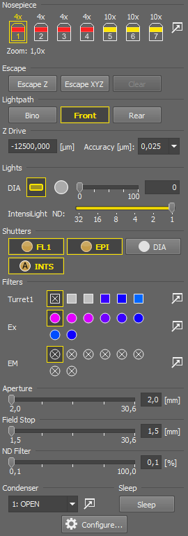
Figure 82.
The NI-E Pad (fully armed) consists of the following portions:
Control the objective changer by clicking on the buttons.
Use the button to select objectives from the database of objectives. Please see Assigning Objectives to Nosepiece Positions where also the objective icons and color symbols are described.
Parfocality Correction indicates whether parfocality (seamless transitions between microscope objectives with minimal or no refocusing) is turned ON or OFF.
Parcentricity Correction indicates whether parcentricity (field of view correction so the sample stays centered when switching objectives) is turned ON or OFF.
Control panels for controlling DIA and Intensilight (EPI) illumination appear if the corresponding devices are connected. AS stands for aperture stop, FS for field stop and ND for the ND filter.  reverts the values back to default. Control the Condenser changer by clicking on the buttons. Use the button to select the condenser from the database.
Control the available filter changers by clicking the buttons. Use the button to select filters from the database of filters.
The filters graphical user interface can be switched between Classic and New in Devices > Device GUI Style.
You can insert an exact value for the Z drive to move to. Confirm it by Enter.
Configure A configuration window appears where it is possible to specify microscope options.
Limits to XY stage and Z drive movements can be specified. Insert maximum and minimum distances for each axis. Just the maximum/minimum of the Z drive can be specified depending on its type (whether it moves the stage or the nosepiece). See for further details.
Select speed and accuracy for the XY and Z motors. Accuracy can be set to XYZ stages equipped with encoder. Open sets the fastest option with the lowest accuracy, while Auto automatically adjusts the accuracy based on the current hardware settings (e.g. objective magnification).
This function guards the stage position in between stage movements so that the stage stays perfectly in its last position thus improving the overall experiment accuracy.
Specify what type of shutters are connected to the ports on the back of the microscope body (none, EPI, DIA, AUX).
Show Sleep enables the user to hide or show the Sleep button on the Ni-E Pad. Show Microscope Settings adds the Current Settings to Microscope Mode section to the bottom of the Ni-E Pad. Select to which microscope mode the current settings will be assigned. Editable name of the selected microscope mode is displayed next to this pull down menu. You can enter arbitrary four characters as a name. If you press the Assign to Microscope button, current settings are assigned to defined microscope mode.
(requires: Local Option)
Apply Parcentricity Offset on Objective change automatically corrects the field of view so the sample stays centered when switching objectives.
Show remote control on pad adds a remote light control to the Ni-E pad. This specifies whether the light is controlled by the hardware or by the software.
Note
Users who want to change the DIA Lamp settings from the microscope body in the Ni-E Microscope Configuration - DIA Lamp must enable Show remote control on pad and then set Rules for the Lightpath - Position to Control by Microscope Body.
Users who want to change the DIA Lamp settings from NIS-Elements in Ni-E Microscope Configuration - DIA Lamp must disable Show remote control on pad. When Show remote control on pad is disabled, control is transferred to NIS-Elements, and lamp power cannot be controlled from the microscope body. The default setting for Show remote control on pad is disabled.
(requires: Local Option)
NIDAQ control On/Off controls the alternative DIA lamp on/off switching. NIDAQ Control Power controls the alternative DIA lamp power. Third party light can be used as well.
Saves the configuration settings into a .txt file using and imports the dialog settings from a .txt file using . During the import, it is possible to select which parameters are imported using the check boxes.
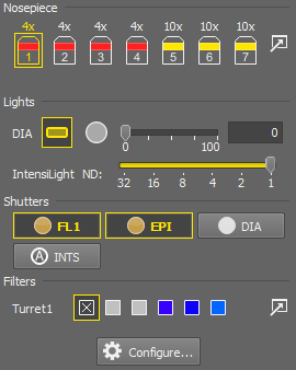
Figure 83.
The Ni-U and Ni-L microscopes are simplified versions of the advanced Ni-E microscope. Please see Nikon Ni-E Microscope for the description.
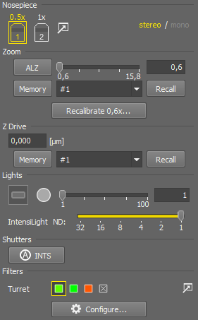
Figure 84. SMZ 25 Pad
Note
Supported models are: 18, 25, 754T, 800, 800N, 1000, 1270, 1270i, 1500
Depending on the type and setup of your SMZ, the control pad can contain different options.
Select the first objective on your nosepiece.
Click and follow the calibration instructions (see: Objective Calibration).
Switch to the next objective, go to
Calibration > Objectives and it.If your microscope has more than two objectives, repeat step 3.
Click the button to move the Z Drive up by the distance specified in the rightmost edit box. Click it again to move the Z drive back to its original position.
The button resets the escape status (“escaped or not escaped”) to “not escaped”. E.g. If you pressed the sequence of buttons: - - , the Z drive would move twice the defined distance up.
This control enables you to specify the zoom value.
(Auto Link Zoom, supported by Nikon SMZ 25 only) can be activated to keep the magnification constant (same FOV) even if the objective lenses are switched: Objective magnification x Zoom = constant.
Zoom slider defines the zoom of the microscope (supported by SMZ 25 only). Use the edit box next to the slider to enter a precise zoom value.
assigns the current Zoom/Z setting to the position selected in the pull-down menu. To recall a setting, turn on and select the setting from the pull-down menu.
The button opens the Manual calibration window used for calibrating the current zoom magnification.
Note
For a correct zoom calibration on multiple SMZ objectives, follow this procedure:
Standard Z Drive control. The only difference from other microscopes is that the units used are millimeters.
Note
Because the minimum step of the SMZ Z drive is 1.6 µm, it is not possible to move exactly by the amounts displayed in the XYZ Navigation ( View > Acquisition Controls > XYZ Navigation ) and by values lower than this step. XYZ navigation is a generic GUI and its values are not changing via Z drive, so SMZ moves to the next step with the best precision which it can. Use 1 and 0.5 up arrow buttons to get over your desired Z value and then precise the number by 0.05 and 0.003 down arrows.
Control panels for controlling DIA and Intensilight (EPI) illumination appear if the corresponding devices are connected.
Configure A configuration window appears where it is possible to specify microscope options.
The bottom limit to the Z drive movement can be specified. Click the button to insert the current position as the limit. See for further details.
Select speed for the Z drive motor.
If any zoom magnifications were recalibrated, they are listed here. They can be deleted one by one or the list can be completely resetted.
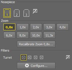
Figure 85. SMZ 1500 pad
The Nikon SMZ product line is very variable, some models are fully manual, some contains intelligent or motorized parts. If you plan to use your SMZ in the manual mode, connect the microscope as Nikon SMZ Manual in the device manager.
See Motorized, Intelligent and Manual Devices.
Pad Options
Specify the objectives mounted to your nosepiece via the button.
Zoom factors selected for display in the configuration window.
You can modify calibration for the selected Zoom. Click the button and proceed to manual calibration.
If a turret is selected in the configuration window, you can select the used filters via the button.
Click this button to specify properties of the SMZ microscope used.
Microscope model. Other options in this window depends on the selection.
Select how many objective positions will be displayed in the pad.
Is the turret mounted? Select this option.
Having this accessory mounted on the microscope changes the zoom factor. Select it if you have it.
You can modify the list of displayed zoom buttons by the and buttons. The button loads the default list of zooms and their calibrations.
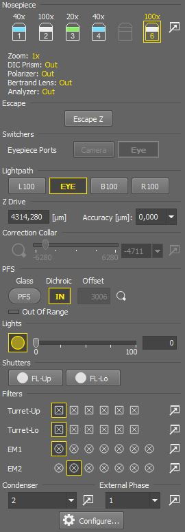
Figure 86.
The Ti2 (fully armed) Microscope Control Pad consists of the following portions:
Control the objective changer by clicking on the buttons.
Use the button to select objectives from the database of objectives. Please see Assigning Objectives to Nosepiece Positions where also the objective icons and color symbols are described.
Note
If the installed nosepiece supports the correction collar, the position number 5 gets disabled.
Press this button to move the Z drive to the position most away from the sample. Use it when changing objectives or slides on the XY stage or during XY stage initialization. When the button is de-selected, the Z drive moves back to the most recent position.
The button is displayed in the escape mode and can be used to clear the escape flag - i.e. stay at the current Z escape position and unlock the Z control.
Camera / EYE notifies about the light path direction if an eyepiece having two paths (eyepiece and camera) is connected.
The light path control buttons correspond to the buttons placed on the microscope body.
Note
Bertrand lens is automatically removed from the light path when switching from EYE to Camera.
Movements of the integrated Z drive are performed by the up/down arrows. Accuracy can be set in the pull-down menu on the right. The Accuracy setting affects the Z drive speed slightly.
Moves the XY stage to the loading position.
This section controls the objective correction collar. The slider and the edit box defines the correction collar position.
Note
If the correction collar is used with a confocal microscope, the recommended pinhole size is 1.2 AU.

Click this button to open the ACC Calibration dialog window. See Automatic Correction Collar Adjustment.
Use the slider to set the correction collar value. Hover the cursor over the slider to display a tooltip table with the cover glass thickness and recommended correction collar values for particular temperatures.
Named presets of the correction collar values to the pull-down menu on the left of this button. Here you can add values to the list, name them and sort them.
If the “Water Immersion Dispenser” device is installed correctly and a water immersion objective is activated in the microscope pad, these three buttons can be used:
Starts supplying water to the tubes and on the objective.
Water evaporates in time. Once initiated, automatic replenishment is started and the period is set to 30 minutes. Shall the water be replenished earlier, use this button.
Empties the tubing. Use this when you have finished the experiment.
See also Using Water Immersion Dispenser.
This optional accessory can be controlled via the pad.
The main button turns the perfect focus system on and applies the current PFS offset. If the current objective supports two materials of the sample carrier (glass slide, plastic dish), a pull-down menu appears next to this button where the actual material in the sample holder shall be selected.
This button moves the motorized dichroic mirror for the PFS in and out. PFS works only if set to the In position.
If the PFS is on, the offset value can be typed right in the edit box.
Turns the PFS on and finds the offset value so that it corresponds to the current Z-drive position.
The light source can be turned on/off using the  button. Use the slider to set the light intensity or enter an exact value (percents or voltage) into the edit box.
In case of LED DIA Illumination the DIA LED button is added to the top toolbar so that it can be used in Optical Configurations as an active shutter.
All available Ti2 shutters are controlled from here. When Nikon Intensilight is connected,  INTS shutter appears. FL-Up and FL-Lo shutters correspond with the shutters in the filter turret.
Control the available filter changers by clicking the buttons.
Use the button to select filters from the database of filters.
Control the condenser changer by selecting a position from the pull-down menu.
Use the button to select condenser from the database of filters.
Can be used to select the External Phase Ring for the eyepiece.
This mode is used to prevent any potentially harmful effects caused by the electronics inside the microscope which may be potentially harmful to the specimen or otherwise interfere with the acquisition process. Use the button to temporarily turn the electronics off and back on.
Display or hide this option in the General tab of the microscope configuration dialog.
Configure Opens the configuration window.
Note
If a halogen lamp is connected to the system, “Mount Halogen Lamp” option has to be checked. This lamp requires an amount of time to be fully turned on and off. You can adjust the On/Off Time [msec] in the edit boxes which delays all experiments using the halogen lamp on/off command.
Does as it says.
Turns the front panel LED diode ON.
Saves the configuration settings into a .txt file using and imports the dialog settings from a .txt file using . During the import, it is possible to select which parameters are imported using the check boxes.
Sets the software limits for the XY, speed and accuracy.
Sets the software limit, speed, Open/Closed Loop Control, accuracy and Keep Z position.
The main box of the Ti2-E has two connectors which can be used to establish a connection using 8 BNC I/O with additional 16 BNC with the Extension box. Select the usage of the BNC connectors in the pull-down menus:
Enables the NIDAQ resource and controls accessories in the Triggered Acquisition and Illumination Sequence windows. PFI is selected per camera.
FIRE signal from the camera is connected to this pin. It enables the user to use the Ti Recipe (recipe is turned on).
copies the camera out signal (works like a hardware “T connector”).
Output signal: Hi = something is moving, Lo = nothing is moving.
Hi = in focus, Lo = other states
Hi = in range but not in focus, Lo = other states
Hi = in focus or in range and over the sample, Lo = other states
Hi = in range, Lo = out of range
If set, Output Signal Toggle on extended IO %d (two state button) or Output Signal High on extended IO %d Firmware Function in the Programmable Buttons tab can be assigned to a joystick button or microscope body button.
Defines the programmable buttons on the microscope body and joystick. Each button can be used to run a specific macro (Run Macro), to run a command (Command List), to capture (Capture button), to switch to a selected light path (Select Lightpath) or to run a Firmware Function.
Note
When NIS-Elements is running, do not assign any Firmware Functions from outside tools and applications. If you still need to assign functions from external tools and applications, close NIS-Elements first.
Macro commands work with the programmable buttons only during the NIS-Elements session and override the firmware functions. When NIS-Elements is closed, all programmable button assignments are restored to the firmware state.
Mounts the LAPP system. If a motorized or intelligent branch is mounted, it is automatically added and cannot be removed.
See: View > Acquisition Controls > LAPP Pad, Motorized, Intelligent and Manual Devices.
This function guards the stage position in between stage movements so that the stage stays perfectly in its last position thus improving the overall experiment accuracy.
The function cannot be used and is automatically turned off when using PFS.
Note
All the commands used in Ti pad for moving Ti accessories are recorded in the Command History ( Macro > Command History).
All the microscope settings done inside NIS-Elements or in the Ti2Control App are stored in the microscope from which they are loaded on startup.
Runs the Ti2 Control where it is possible to set microscope accessories and options and execute “Assist Guide” suitable for making preparations of microscope observations. See the “Ti2 Control manual” book for more information.
Place the fluorescent beads sample (sample where PSF can be obtained) onto the stage. Or else, place the beads sample or biological specimen on the stage. In case of beads, find the less densely populated region where the number of beads within the FOV is about 10.
Click on the
 Live button and enable
  Keep Auto Scale in the Live window.
Display the Histogram (
View > Visualization Controls > Histogram  ) and adjust light and exposure time so that no saturated pixels are present in the image. After the adjustment, Freeze
  the live image.
Click on the
button in Ti2 Pad to show the ACC Calibration dialog window.Select the Sample Type in this window. Click on to show the Live window.
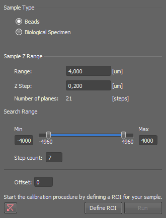
Figure 87. ACC Calibration dialog window.
Move the motorized stage to place the target image (isolated beads or cells of interest) in the center of the FOV and bring it into focus. Set ROI to the target image in the Live window.
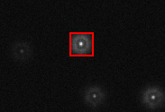
Figure 88.
Click on in the ACC Calibration window to close the Live window.
Sample Z Range and Search Range should be set as follows based on the type of objective.
Table 2.
Objective/Sample Type Sample Z Range Search Range Range* Z Step* Min Max Step Count 100x Oil, Beads 5.0 0.20 -4960 13280 7 100x Oil, Biological Specimen 2.5 0.05 -4960 13280 7 60x Water, Beads 30.0 0.20 -6240 6240 7 60x Water, Biological Specimen 15.0 0.05 -6240 6240 7 Click in the ACC Calibration window to run auto correction. Z-Stack image acquisition is run and correction collar is adjusted automatically. When the adjustment is finished successfully, the correction collar is moved to the adjustment position.
Note
Approximately a two hour warm-up period is required after switching the microscope on.
For the correction ring adjustment, images acquired by the Epi-FL illuminator unit can be used as well as N-SIM images.
Hardware restrictions
Please use one of the following cameras: Andor iXon3, Andor iXon Ultra or Hamamatsu ORCA Flash4.0. For the Z-Stage, please use MCL Piezo Z. If ACC is performed with a camera or a Z-stage different than those mentioned, correct results cannot be obtained.
Place the fluorescent beads sample (sample where PSF can be obtained) onto the stage.
Find the less densely populated region where the number of beads within the FOV is about 10.
Click on the
Live button and enable Keep Auto Scale in the Live window.Display the Histogram (
View > Visualization Controls > Histogram ) and adjust light and exposure time so that no saturated pixels are present in the image. After the adjustment, Freeze the live image.Move the motorized stage to put the isolated fluorescent bead image in the center of the FOV and bring it into focus.
Tip
Vertical movement can be adjusted by the mouse wheel after clicking on the live display.
Click on the Z tab. Press
 Symmetric mode defined by range and then
  Home to set the current focus position to the center of the stack.
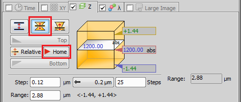
Figure 89.
Set the Z stack so that the Z-Step is 0.12~0.16 μm with 25~30 Steps.
Click
 Run now to start image acquisition.
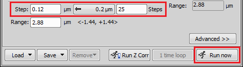
Figure 90.
On the acquired image window, click on the Show Slices View icon to show the cross-sectional images of XZ and YZ.
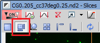
Figure 91.
From the Mode pull-down menu select Slices.
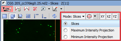
Figure 92.
Set the display magnification to 200%.
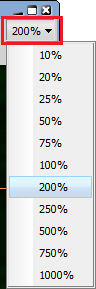
Figure 93.
Open
View > Visualization Controls > LUTs  and lower the upper limit of LUTs to make it easier to see the defocus spread.
Move the correction ring by one position to refocus.
Press
Home of the Z series tab in the ND Acquisition (About ND Acquisition) to set it to the center position of the Z stack.Click
Run now to acquire Z stack images in the same way.When the capturing is done, move the position of the correction ring and repeat the same process.
By changing the position of the correction ring, compare the series of Z stacks and select the position so that the symmetry in the Z direction is the best. Adjustment of the correction ring is completed.
In the examples below, the symmetry is best at 0.18.
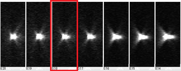
Figure 94.

Note
Approximately a two hour warm-up period is required after switching the microscope on.
For the correction ring adjustment, images acquired by the Epi-FL illuminator unit can be used as well as N-SIM images.
Suppose the device is connected properly, a Water Immersion Dispenser section appears int the microscope pad. An immersion objective must be selected in the nosepiece to have all the buttons enabled.
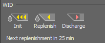
Figure 95. WID pad before initialization
Click the button to add the first water on the objective. A progress dialog appears.
Note
If the objective is in focus position, it will move to the escape position for the time needed for initialization.
Information about the time to the next automatic replenishment starts appearing below the buttons. E.g.: Next Replenishment in 30 min. If you need to replenish the water sooner than indicated, click the button.
After the experiment is finished, discharge water from the tubes by the . This is important in order to keep the tubing clean. If you forget, the software will prompt you to discharge the dispenser upon exit.
At last, do not forget to dry up the objective and the slide so that these parts stay clean too.
Tip
Behavior of the device can be customized in Windows registry on the following path:
HKEY_LOCAL_MACHINE\SOFTWARE\Laboratory Imaging\Misc\Ti2\WID
Settings for each objective can be edited as well (there are sub-folders named with objective codes).
Note
All Water Immersion Dispenser events are logged per microscope connection in a separate file into the following location:
C:\ProgramData\Laboratory Imaging\Platform\Logfiles\WIDRecord_*.log
where * is the date.
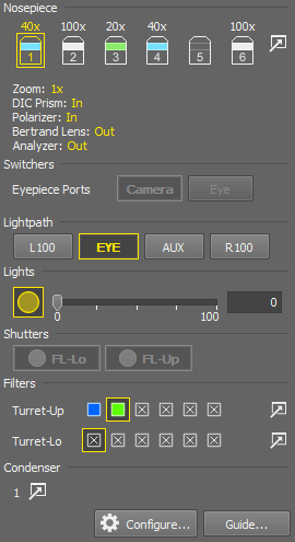
Figure 96.
Most features of the Ti2-A Microscope are similar to the Ti2-E Microscope. Main difference is that Ti2-A microscope uses only intelligent models of Shutters, Filters and Condenser.
See Motorized, Intelligent and Manual Devices.
Please see Nikon Ti2-E Microscope for full description of the microscope features.