
 Lightpath Scheme
 The full microscope configuration is displayed visually and controlled by the user using a mouse.
Simplified work with multi-device hardware configurations. Double-clicking on a device in the scheme opens its control pad.
Multiple hardware configurations (multiple independent microscope setups) can be set and easily switched between them.
Lightpath concept - optical paths are colored to match the defined wavelengths. The program watches the current hardware state and produces a warning if image acquisition will not be possible. See Lightpath tool bar.
Simplified definition of Optical Configurations – only devices enabled in the current hardware configuration are visible within the
 View > Acquisition Controls > OC Panel
  panel.
Determine which devices are used together, other devices can be turned off.
By default, the “Acquisition” hardware configuration is created. The user then adds the connected Cameras and Devices using the  buttons. Lightpath combinations are automatically calculated in the Lightpath Selection table. The user usually does not need all the devices connected so any camera/device can be turned off creating a new device combination. This new “hardware configuration” can be saved by clicking on the Create New Hardware Configuration button and a new tab with a given name is created. The user can switch to a different configuration using the tab and clicking , using the Devices > Select HW Configuration command or on NIS-Elements startup. Devices which are disabled for the selected configuration are not loaded and can be switched off to make the startup faster.
Groups devices (from the hardware configuration) used in one observation mode (EPI, DIA, TIRF, confocal, etc.).
The table inside each hardware configuration contains “Light Paths” which represent all available light paths (light tracks between the cameras and illumination devices present in the current configuration). Simply stated a light path tells which devices are used at the same time. Click on the name of a light path to highlight it in the image. Check Edit to select which light paths will be shown in the current hardware configuration.
Different light paths are usually saved under different hardware configurations to make the microscope operation most powerful and efficient.
Note
Hardware buttons of the Nikon Ti2-E microscope can be set to switch to a predefined light path. In the Devices > Device Manager  , select in the context menu over the microscope, switch to the tab, choose a button and click on its drop-down arrow, click Select Lightpath and set a light path from the list.
If you are running NIS-Elements for the first time, you will be asked to select a microscope and define the first hardware configuration. Click to open the New Setup window. Select the microscope connected to your computer and click . The Device Manager window opens. Use this manager to add all cameras and devices connected to the microscope, then create hardware configurations and lightpaths.
You will be asked to select a hardware configuration every time you launch NIS-Elements (unless you selected the Select automatically on startup option). Only the cameras and devices present in the selected configuration will be connected. You can switch to another hardware configuration later in the device manager or using the Devices > Select HW Configuration command. If you need to create a new hardware configuration without loading an existing one, please select the predefined configuration called Offline Analysis during and then create a new configuration in the Devices > Device Manager .
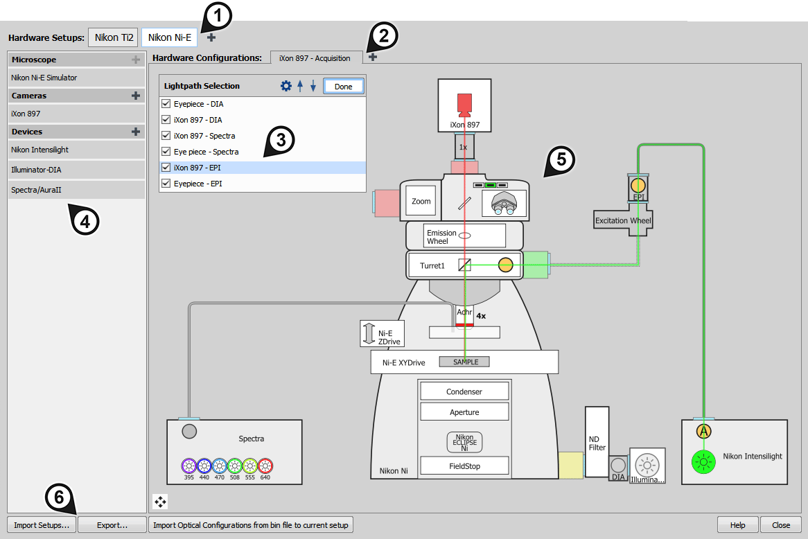
Figure 48. Device Manager Overview
Hardware Setup tabs - select which microscope is used. More setups are added by the
button.Hardware Configuration tabs - select a hardware configuration. More configurations are added by the
button.Lightpath Selection table - displays all available light paths for the current hardware configuration and selects the active light path. Use to select which light paths will be hidden/shown and change their order using the

 arrows. To add/remove the light path with all devices, click
  Settings... and check/uncheck All Devices.
Microscope/Cameras/Devices list - shows all connected microscopes, cameras and devices. To add more, use the
button.Microscope scheme - shows a visual microscope scheme of the current setup. The system can be configured directly from this scheme using mouse dragging and context menus.
Device Manager Settings - exports the selected hardware setups (hardware configurations, light paths, optical configurations, etc.) into a .dat file whereas can be used to load the previously exported setup. opens this help page.
Display the device manager by the
Devices > Device Manager command.Select and activate a hardware setup and a hardware configuration in the top tool bar. In case you run the device manager for the first time, you will be prompt to select a microscope from the list of installed drivers. This will create a hardware setup and hardware configuration.
Click the Cameras
caption to add a camera, click Devices to add a device such as an illuminator, a motorized stage, etc.Select the model of your device from the list and click / button.
Note
Only cameras and devices whose driver was selected during the installation process are listed.
A drawing of the camera or device appears in the window either mounted to a default position or floating next to the microscope. Drag it by mouse so that the visual position matches the physical setup. Available positions are highlighted yellow.
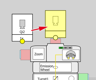
Figure 49. Drag a camera or device to a correct position
Note
Non-standard mounts which are not recognized by the software can be connected to the microscope by adding the Coupler Universal device which can connect any camera or device to any port. The Coupler Universal Switcher can connect two cameras or devices to a single port.
Right-click the camera or device to display a context menu where various actions may be made.
Before you get to work with NIS-Elements, all hardware accessories should be connected properly to the system. In most cases, the following basic procedure is sufficient to connect a device successfully:
Install NIS-Elements, and select the appropriate device(s) during the installation.
Connect the device to the PC and switch the device ON.
Run NIS-Elements, and run the
Devices > Device Manager command to open the Device Manager window.Select a microscope hardware setup or create a new one.
Click the Add button next to the Devices caption to add the device to NIS-Elements.
Select the device from the list of installed devices and click .
Click on the device in the scheme and drag it to the highlighted hotspot so that the connection matches your physical microscope setup.
Create a hardware configuration with light paths suitable for the experiment.
If a peripheral device is connected to NIS-Elements, some extra commands and features become available. This concerns typically motorized XY stages and Z drives, but also other devices.
Note
MULTIZOOM AZ100M, ECLIPSE LV series, ECLIPSE MA200, or ECLIPSE L200N/300N microscopes can not be connected from NIS-Elements while the setup tool of each microscope is active. To connect any of these microscopes to NIS-Elements, exit the setup tool and then run NIS-Elements.
Renaming of devices
Either logical or physical device can be renamed by the user. Just right-click the device name and select the Rename... command from the context menu. The user-defined names can be handy in two cases:
You are using two logical devices having matching names, but you need to uniquely identify them (e.g. from a macro).
You are used to call a device with another name and would like to rename it in order not to be confused by the predefined name any more.
 will appear in the main toolbar of
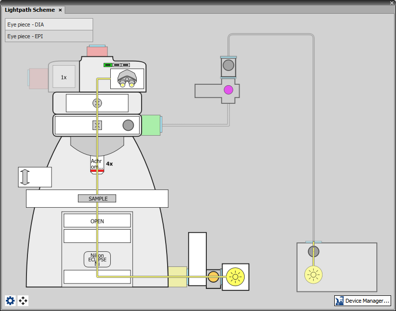
Figure 50. Lightpath Scheme pad
This panel invoked by the Devices > Show Lightpath Scheme  command displays the active hardware configuration. Physical tracks of the light - so called lightpaths - are indicated in the scheme by colorized lines. If the light path is blocked (dashed line), a warning symbol (
 ) appears by the device which prevents the light from passing through. The same warning symbol displayed in the list of lightpaths indicates that some device in that particular light path are not set correctly. Such lightpaths will not be saved. Thanks to this indication the user can quickly detect possible errors in the setup (e.g. wrong filter cube assignment).
Microscope buttons, shutters, lights, etc. can be controlled directly by clicking on them in the scheme. Double-clicking on a device opens its control pad. Devices not participating in the current light path are outlined in gray and can still be controlled.
Note
Stimulation light paths are not shown in the Lightpath Scheme. If you need to use the stimulation light path for acquisition and not only for stimulation, enable the acquisition light path under the button in the Devices > Device Manager window. If this light path is missing, make it visible by clicking the Settings... button and checking it.
Context menu over a device
Finds and activates a light path being the most similar to the currently selected light path and containing the device being clicked at the same time.
Specifies further rules for the clicked device in the current active light path.
Controls the device state/position/settings using Optical Configurations when the current light path is selected.
Does not change the device state/position/settings when the current light path is selected.
A shutter can be used as “active” (preferred) in the current light path and all other shutters will be set to their default behavior.
Always keeps the device in the position selected from the drop-down menu when the current light path is selected.
Lightpath Scheme Settings In this window, you can change the display colors of the light paths, display or hide the list of light paths within the panel, display or hide text labels over the devices and turn on/of the warning message when a light path is changed and positions of non-motorized devices do not match.
 Fit to Screen
 Adjusts the zoom so that the microscope scheme fits into the Lightpath Scheme pad. The scheme can be zoomed in/out using the mouse wheel.
 Device Manager...
 Opens the Devices > Device Manager window.
NIS-Elements handles hardware accessories using the concept of logical devices. There are features of different hardware devices which equal and therefore can be controlled equally. Such features are called “logical devices”. A typical logical device is Stage XY. Microscopes can be equipped with different XY motorized stages, although - regarding the user interface - they behave equally. One physical device (a piece of hardware) can contain one or more logical devices the list of which appear in the Device Manager after the connection is established.
Display the filter changer control panel (
Devices > Filters and Shutters or Devices > Microscope Control Pad  ).
).Click the settings button
 , a window appears.
Select one of the available positions which the filter will be assigned to.
Click the button, a list of available filters appears.
Select the filter name from the list and confirm it by .
The filters can be moved within the already defined positions using the Up and Down arrow buttons.
The analyzer is a polarizing filter placed in the optical path between the specimen and the lamp. The logical device offers two states: ON (inserted) and OFF (extracted).
This logical device is used for controlling apertures in the light path. It is used in complex microscopes rather than as a standalone device. Two parameters can be typically set for aperture devices, the state (on/off) and aperture size.
A condenser is a two-lens combination located next to the illumination source in the optical path. Its purpose is to collect light and direct it to the specimen being examined. The corresponding logical device relates to a changer of different condensers.
This logical device controls filter changer movements. There can be several filter changers connected to NIS-Elements at a time. Each filter changer needs to be set up - filter types shall be assigned to positions of the changer:
Note
When browsing the list of filters, details about the currently selected filter are displayed on the right side of the window.
This logical device is used for controlling the specimen illumination remotely. There is no standard dialog box for the illuminator control. Each device handles this logical device via a user interface specially designed for it - typically containing one button for switching it on/off and a slider for regulating intensity.
Some microscopes have more than one port where it is possible to attach a light source or a camera. This logical device can switch the illumination between these ports.
This logical device is used to group standalone logical devices used in certain microscopes. To control the logical devices of a microscope from one control panel, select the Devices > Microscope Control Pad command.
This logical device serves for controlling microscope objective changers.
See Assigning Objectives to Nosepiece Positions, Motorized, Intelligent and Manual Devices.
A neutral-density filter is a light absorbing filter whose absorption spectrum is moderately flat. It is used to reduce the illumination intensity within the optical path. The logical device offers two states: ON (inserted) and OFF (extracted).
Perfect Focus System - this logical device corresponds to the PFS physical device available with Nikon TE2000/TI microscopes.
This logical device can control shutters installed in your system. This device is handled via the Devices > Filters and Shutters control panel or straight from the microscope control pad. You can select the type and rename the shutter by running a contextual menu command either within the Filters and Shutters control panel, Device Manager window, or in the main toolbar.
Note
There was a restricted number of shutters which could be connected to the system in previous releases of NIS-Elements and they were identified by Type (DIA, EPI, Aux1, etc...). The current version supports identification of shutters by custom Names, but the Type attribute can be still found in some windows (or used in some macro functions). This is to ensure backward compatibility.
This logical device is used for controlling the zoom factor.
Run the View > Acquisition Controls > Zoom Manual Pad  command to adjust the zoom settings.
For the purposes of this manual, we distinguish the following device types. Each type provides a different level of control from the software.
It cannot be controlled via the software neither the software is aware of its current state. For the purposes of image acquisition, the current state of such a device shall be set in the software manually so that the meta-data of the acquired image would be correct. This typically concerns a manual nosepiece or a filter changer.
The current state of the device is displayed within the software GUI, but the device cannot be controlled.