Having NIS-Elements installed and all hardware accessories set up within the Devices > Device Manager  window, you can start capturing images. Let's begin with the simplest case.
Turn the connected camera and other devices ON and start NIS-Elements.
Select a suitable hardware configuration on startup.
Make sure the Compact tab is selected with the
 Acquisition
  panel displayed on the right.
Select a lightpath which includes a camera (1).
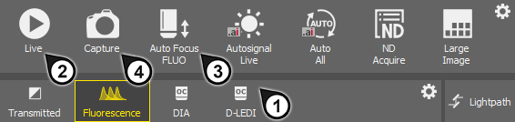
Figure 138.
Display the camera image by the
 Live/Smart Live tool (2).
Adjust Exposure on the camera pad to get a nice image of the scene.
Focus on the scene by the

 Short/Long range Auto Focus tool (3).
Capture the image by the
Capture tool (4).A new image is opened automatically and named “Captured ...”.

Figure 139. Light path tool bar for a configuration with two different cameras
Buttons for switching between lightpaths available for the current hardware configuration are displayed below the tool bar of the Acquisition panel. An icon is displayed on each button to indicate the type of lightpath:
 Bightfield
 Brightfield acquisition.
 , DIA, EPI
 General acquisition based on optical configurations. Different optical configurations can be created within such a lightpath.
 Fluorescence
 Multichannel acquisition based on “experiment settings”. With this concept, the user specifies a set of fluorescence dyes to be used within an experiment. The program calculates the hardware settings automatically.
See Multi-channel image acquisition via experiment settings.
 , DIA, EPI
 General observation lightpath. Different optical configurations can be created within such a lightpath.
 Lightpath
 Click this button to open the Lightpath Scheme  panel which visualizes the current lightpath and may indicate possible errors in the setup.
In case there are some lightpaths you will not use, you can hide them from the tool bar. Click  Configure... or using the
  RMB anywhere in the tool bar and select to open the User Visible Buttons window.
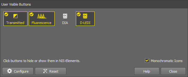
Figure 140.
(De)select any lightpaths you do not want to display. The ones with the tick icon will be displayed in the tool bar.
Optionally change the icon color (color or monochromatic icons).
If you are a user with the privilege Modify devices and light paths, you can even hide some light paths entirely. To do this, use the
Configure button in the same dialog window to open the Button Order and Visibility System Defaults window.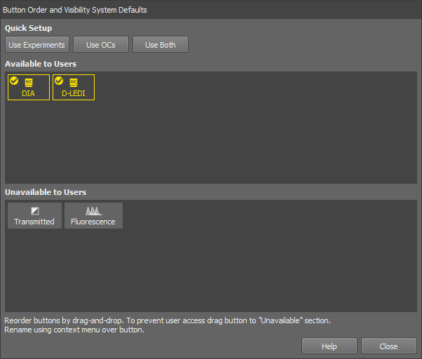
Figure 141.
Drag the buttons to the bottom area to hide them to the users. Change the order of the available buttons by moving the buttons in the Available to Users area. Quick single-click button setups are available in the Quick Setup section in the top of the window. Rename the button in the context menu over the button.
Click to confirm the selection.
Select a lightpath button with the icon . A tool bar with optical configurations appears below the lightpath buttons. The usage of optical configurations (OCs) within the Acquisition panel is the same as in the previous versions of the software where optical configurations were global. The difference is that only OCs created within the currently selected lightpath are displayed here and in the main tool bar of NIS-Elements. Other optical configurations are available only after switching the lightpath.
Note
To change the described default behavior, click RMB in the OC tool bar and select Show OCs from all Lightpaths. Moreover, particular OCs can be hidden from the tool bar by the Select Visible Configurations command from the same context menu.
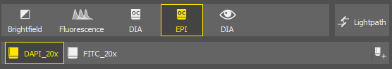
Figure 142.
 Add
Add Click this button to call the Calibration > New Optical Configuration  command.
Select the Fluorescence lightpath to display the “experiment tool bar”. Here you can define different presets for multi-channel acquisition.
Let's suppose you are creating a simple experiment consisting of channels DAPI, FITC, TRITC.
Select a lightpath
Make sure the
Fluorescence light path is selected in the Acquisition panel.Add a new experiment preset
Specify channels
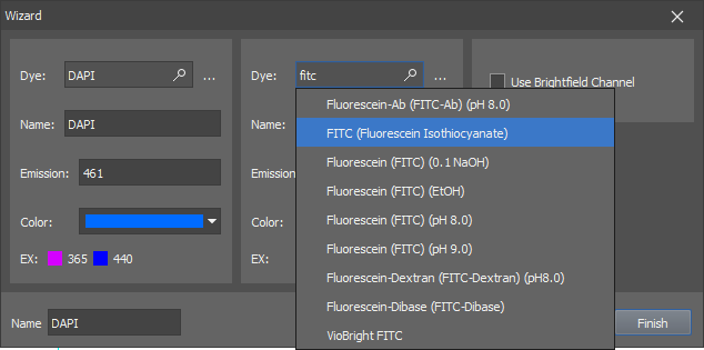
Figure 143. Experiment wizard.
Type “DAPI” in the first search field, select the actual dye you will be using and confirm it by Enter. Another search field appears. Add the FITC and TRITC dyes as well. Optionally, select the Use Brightfield Channel box to capture the brightfield channel too.
Confirm the experiment settings
Click to close the window. The newly created experiment will be activated and a button for each channel will appear below the selection box.
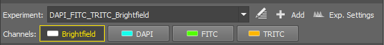
Figure 144. Experiment tool bar
Singe Channels and All Channels options are present by default.
All Channels - automatically calculates the possible dyes for acquisition based on the experiment excitation wavelength and filter settings. All channels are acquired during the capture.
Single Channels - all possible dyes are calculated, however just the single (selected) channel is acquired during the capture.
Adjust light power and exposure for each channel
Below the experiment tool bar, the experiment pad (Experiment pad) appears instead of the usual camera pad. It consists of a simple control panel for each channel where illumination power and exposure time can be adjusted. Only one channel can be active at a time.
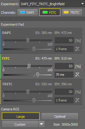
Figure 145. Experiment Pad
You can:
Run the live image by the
Live/Smart Live tool.Activate the split view by the View > Image > ND View > Switch to Split Component View tool in the image tool bar.
Switch between the channels within the experiment pad and adjust the exposure and illumination power so that the live image is as you need. If you need to make any changes in the preset, use the
 Exp. Settings button, to edit it. See Adjusting and managing experiments.
Use the
Capture tool to capture a single multi-channel image.
The Experiment pad is different for different microscopes (Microscopes). For Nikon Ji, it looks as follows:
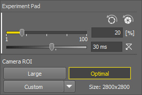
Figure 146. Experiment pad
The first slider sets the exposure of the connected camera. Move the slider or enter a specific value into the edit box.
The second slider sets the illumination power of the connected illumination device.  resets the illumination power value to default.
 Apply Opened Aperture Brightfield Service Settings
 Applies the opened aperture settings (set in Service settings ) for the currently selected objective.
 Apply Closed Aperture Brightfield Service Settings
 This option has to be enabled in the Service settings (Show Closed Aperture button for 4x objective on ACQ pad) first. It applies the closed aperture settings for the currently selected objective.
Camera ROI
The system offers the users three pre-defined ROIs and a custom one. All of the ROIs are available only if they are different from each other.
ROI set to the size of the full sensor.
Defines the ROI size (Define ROI...), specifies which buttons are shown on the pad (ROI Buttons), changes the custom ROI size and saves (Save ROI...) or loads saved ROIs (Load ROI...).
The experiment is characterized solely by dyes, and the system automatically identifies the appropriate light path configuration for each dye. The light path settings can be adjusted manually by opening the  Edit window:
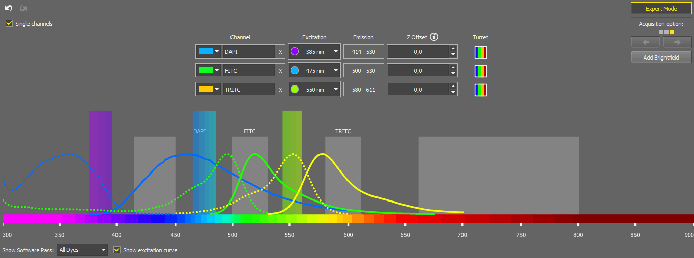
Figure 147.
Here you can change the color of a channel, rename it, delete it (), change its excitation wavelength (when switched to ), change the Z offset, or add a Brightfield channel (Add Brightfield).
The Single Channels experiment is created to efficiently examine an unknown sample by enabling the selection of any light source wavelength and viewing the results in a live window with a single channel. While the setup is similar to the corresponding channel in the "All Channels" experiment, operating it is simpler due to having a LUTs graph and a single channel tab in the live window. Checking the Single channels option means that even in a multi-channel experiment, only one channel is captured at a time. When you create a new setup (in the Device Manager) for the first time and have already created a reasonable All Channels experiment, the system automatically generates a corresponding Single Channels experiment. The behavior of the “Single Channels” experiment mirrors that of turning off all channels except the current one in the “All Channels” experiment, which can be done through the context menu over the channel buttons.
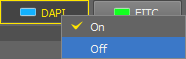
Figure 148.
The Acquisition option on the right means that for a given experiment (given dye) a number of possible configurations (each one shown as a square) have been found and can be used for acquisition. Move between the configurations using the arrows.
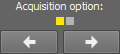
Figure 149.
The spectrum preview below shows the software pass for the channel selected in the drop-down menu. Excitation curve can be shown in the preview by checking Show excitation curve. Once you are done with the adjustments, click to confirm the settings.
The experiments can be managed through Exp. Settings:
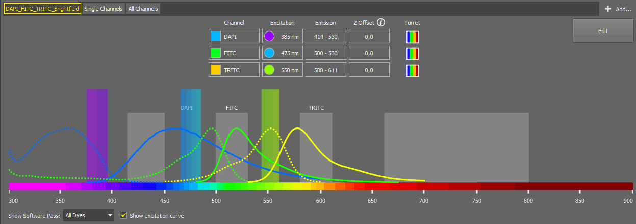
Figure 150.
Here you can check all the channel information for each channel selected in the first drop-down menu. More channels can be added using  Add (see Multi-channel image acquisition via experiment settings). By clicking , you are redirected to the editing window described above.
Parfocality ensures seamless transitions between microscope objectives with minimal or no refocusing, allowing for consistent focus adjustments during magnification changes. Experiment parfocality can be set in three different ways:
Automatically - using the context menu command over the image area (Experiment Parfocality Correction > Find Automatically).
Manually - by setting the Z Offset values in the
Edit window.For experiments excluding brightfield - using the context menu command over the image area (Experiment Parfocality Correction > Save Channel Parfocality Offsets).
Sample navigation is integrated into the Compact layout to control Ji and Ti2 microscope systems. Relying on the geometry of the known Ji/Ti2 microscope holders, this improves the identification of sample location, with added functionality for automatically scanning of slides, wellplates, and dishes. The pad can be opened as a separate window using the  button.
Note
To use the Sample Navigation panel with the Nikon Ti2 microscope, Z focus has to be calibrated first (see Service settings ).
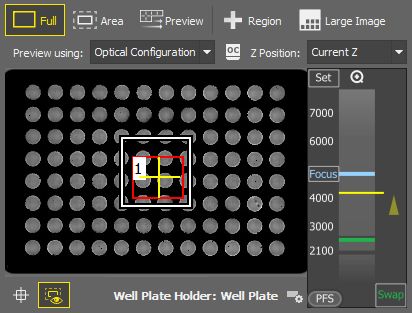
Figure 151. Stage tab
Well Plate Holder Option to choose the relevant holder from the database. The holders on the Ji system are calibrated via the Ji Tools utility, while the calibration of the holders on the Ti2 system is done through the Service settings dialog in NIS-Elements. The Z coordinates used in automatic functions (Detection, Scanning, etc.) for the selected holder are saved in the Service settings .
 ROI
ROI Displays the preview of the scanned ROI. To edit the ROI, select the  Full mode and click on the ROI edge. Confirm the ROI by RMB.
 , Scan Overview, Rescan Overview, Scan ROI, Rescan ROI
 Scans or re-scans the sample area (depending on the selected holder) using the brightfield settings set in the Devices > Service Settings  window.
 Show ROI
 Shows/hides the ROI in the preview area.
Context menu over the Preview
Starts scanning the defined ROI sample area.
Opens the scanned overview or ROI as a new image document.
Z Navigation
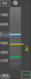
Figure 152. Z Navigation
The vertical column represents the entire Z dimension, with the blue horizontal line indicating the Focus position, the yellow line representing the current position, and the green line denoting the swap position.
Sets the current Z position as the “Focus” position. A tool tip over the button shows its Z value.

 Zoom in/out
This button appears only when working with Slide samples and resets the focus value to default.
Moves the Z stage to the predefined focus position. A tool tip over the button shows its Z value.
Turns the perfect focus system (PFS) on and applies the current PFS offset.
Moves the stage to the swap position - a safe position for changing the samples. A tool tip over the button shows its Z value. This value is calculated automatically during the holder calibration and cannot be changed.
This tab supports navigating in the ND2 documents having well plate metadata.
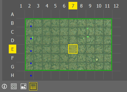
Figure 153. Document tab

Displays the summary labeling and selection information.
 Scheme
 Displays a well plate scheme.
 Images
 Displays captured images as the wells.
 Overlay
 Displays the images together with defined labels and selection.
The Devices > Service Settings window allows adjustments to the microscope and camera settings which are applied to the well plate overview scanning. Settings adjusted here also influence the acquisition controls in the Acquisition Panel.
Depending on the microscope model, some of the options could not be available.
Overview and Plate scanning in Sample Navigation (Nikon Ti2)
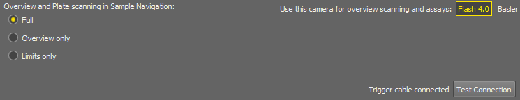
Figure 154. Overview and Plate scanning limits.
Sets the limits to the user controlling the Sample navigation panel. Full sets the full control of all panel features, Overview only limits the control for a basic overview and Overview/ROI (re)scanning, whereas Limits only leaves the user with just a simple stage observation and possibility to change the sample holder.
Select a camera used for scanning the overview in the Sample Navigation and Assay.
Click this button to test the triggering cable connection.
Camera
Specifies the scanning settings for the particular camera.
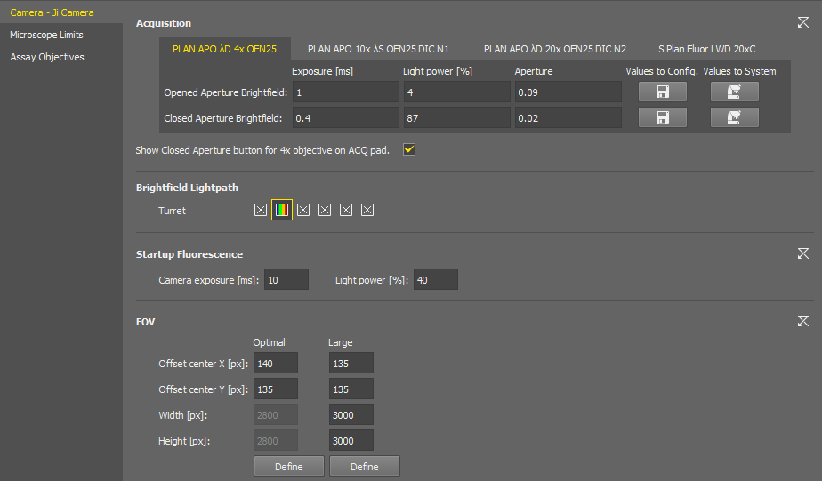
Figure 155. Service Settings for the Nikon Ji.
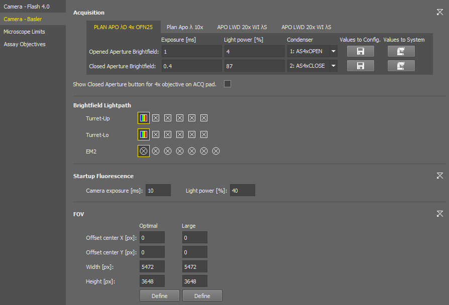
Figure 156. Service Settings for the Nikon Ti2.
You can set the exposure time, light power and select a condenser or aperture for each objective of the current nosepiece configuration. Switch the tabs with the objective names to move between the objective settings.
 assigns the current system brightfield settings to the automatic scanning configuration, whereas the
  Values to System button sets the brightfield acquisition settings to the system as the current brightfield settings.
Shortcut buttons for applying the opened and closed aperture values ( ) are available in the Experiment pad for brightfield experiments. The closed aperture button is enabled here (check Show Closed Aperture button for 4x objective on ACQ pad).
Select the filter changer positions to be used in the experiment.
Camera exposure and light power values used for the start of the AutoSignal.ai algorithm.
These ROIs are integrated into the Experiment pad. Both ROIs can be adjusted here using .
Size of this FOV (camera ROI) is calculated automatically for each hardware configuration to prevent shading on image borders. When turned on in the camera pad, it is placed in the center by default. Here you can shift it by defining the offset.
A user-adjustable FOV (camera ROI) which is used with the continuous scanning procedure (e.g. well plate overiew).
Microscope Limits (Nikon Ji)
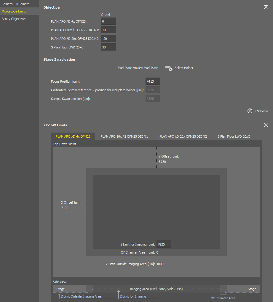
Figure 157. Microscope Limits Service Settings of the Nikon Ji.
Sets the Z positions offsets between the current objectives.
Specifies the sample holder ( Select Holder) and can be used to adjust the focusing position for the Sample navigation . The Z Scheme explains the focus position.
A drawing of the currently selected sample holder containing its dimensions and movement limits set within the software is shown in this section. Z imaging limit can be set in the middle edit box for each objective (switch the tabs to move between the objectives). Side view of the imaging area is depicted in the bottom.
Microscope Limits (Nikon Ti2)
If the system is not calibrated yet, click .
Select a slide holder for calibration and click .
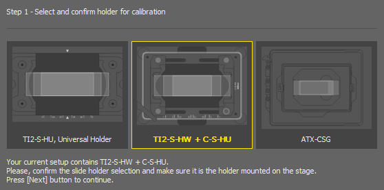
Figure 158.
Even if you plan to use a well plate, the proper Z calibration needs to be done on a slide.
Run
Live and focus on the slide sample either manually or using the Auto Focus. The Z Scheme explains the focus position.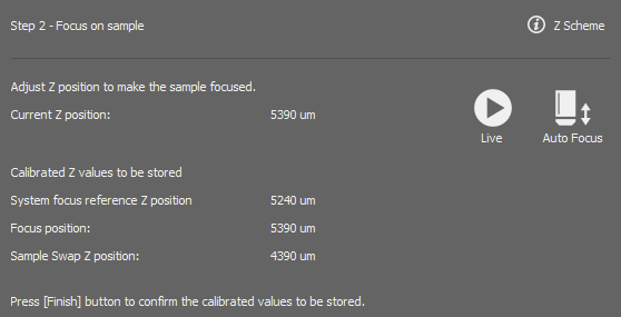
Figure 159.
Once in focus, click .
Sets the Z positions offsets between the current objectives.
Calibrates the Ti2 Z drive so that it can be used in the Sample navigation .
You can repeat the calibration by clicking or adjust the Focus Position in the edit box. The  button sets the value back to default.
Sets the global top limit position for the 4x objective.
Assay Objectives
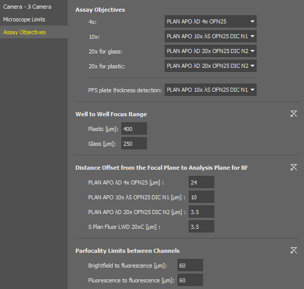
Figure 160. Assay Objectives Service Settings of the Nikon Ji.
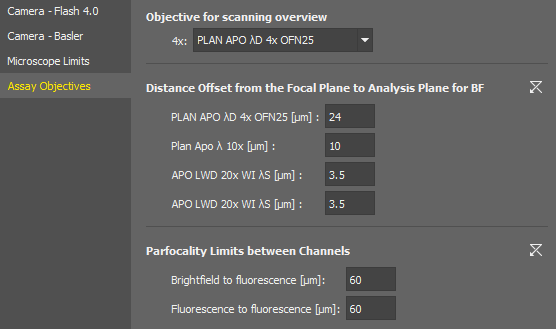
Figure 161. Assay Objectives Service Settings of the Nikon Ti2.
Here you shall assign actual objective models to be used with the assays.
The focus range used after moving to an adjacent well. It should be calculated as:
Maximum possible difference between well plate bottoms of adjacent wells caused by inaccuracies in the manufacturing process.
An extension of the range which ensures the auto focus would work even if iw = iwmax.
The distance to be moved after automatic focusing to see the specimen. This value is set for each objective in the nosepiece.
Specifies the maximum allowed difference of focus when switching between different channels within one experiment.