

Run the Devices > Initiate loader command or click the button on the Slide Loader pad. A warning box appears.
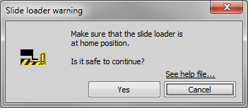
Figure 744.
Check whether there is a risk of collision between the slide loader arm (gripper) and the motorized stage. If collision might occur, click , disconnect the slide loader in the device manager, turn it OFF on the rear panel of the device and move the arm manually to its home position away from the stage. The home position is when the gripper arm is facing the cassettes and is retracted so there is no risk of collision with either the cassettes or the XY stage.
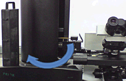
Figure 745.
If you had to disconnect the slide loader, turn it back ON. Then reconnect it to NIS-Elements in the Device Manager and restart the initialization.
If the motorized stage is clear to move, click to proceed. Once more, a warning appears.
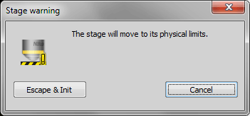
Figure 746.
Make sure that the stage cannot collide with a microscope objective or a condenser (see Devices > Initiate stage) and proceed by the button.
Run the Enable Objective Clearance command. The pictured window appears.
Check the box and the clearance operation will be performed every time an objective is changed or the stage is initialized. If not checked, no action will be taken.
Adjust the Objective distance value which is a distance that the Z drive will travel of the current position.
Confirm the settings by pressing .
Click
 Add, select objectives for the calibration and click .
Click
 Start Capturing on the first objective, position your sample to target reference objects with the crosses and click
  Capture.
Do this again for the second objective. Compare the capture results and make sure they are correctly positioned.
When done, click
 Finish. The new offset is calculated and listed in the table.
enter the intended Z-step value
click the nearby “default value” button.
click the arrow buttons, move the slider, or rotate the mouse-wheel to browse the predefined values.
Brightfield - standard contrast based criterion
Fluorescence - suitable for fluorescence microscopy
Confocal - criterion based only on the intensity values. Can be useful in confocal microscopy.
Yeast, Bacteria (Ph) - a criterion optimized for yeasts under phase contrast (Ph) microscope.
Camera exposure time is not compatible (too short or too long) with the speed of your Z drive.
The automatically calculated coarse step is too large and the specimen is thin so it does not come into focus at all.
Devices > Scan (if the List of Points option is selected in the Devices > Scanning Setup)
Applications > 4D > Define/Run ND Acquisition (req. ND module)

The Device Manager is designed for managing and configuring hardware accessories such as Cameras, Illuminators, Motorized stages, Microscopes, Filters, Shutters, Z drives, etc. Please see Device Manager.

Opens the Lightpath Scheme pad showing the current microscope configuration with visible light paths.
Opens the Setup and Configuration dialog window used for loading a selected hardware configuration. If the Select automatically on startup option is checked, the selected hardware configuration is loaded automatically on NIS-Elements startup without showing this dialog.

Note
Sufficient user rights are required for this function to be accessible.
Opens a dialog where microscope and camera settings for well plate overview scanning can be adjusted.
The window is closely described here Service settings .
(requires: Stage)
The Initiate Stage command detects the stage XY movement boundaries. Before the maximal travel range initialization is started, make sure that the stage cannot collide with a microscope objective or a condenser! Then press to initialize the stage, or .
Figure 743.
(requires: Slide Loader)
This function initializes the slide loader - the XY stage will move to its outer limits. To perform this action safely, follow this procedure:
(requires: Z Drive)
For some devices, the Z calibration is necessary. If the Calibrate Z command is present in the Devices menu, that is the reason. The Z calibration can be done during the stage initialization or using this command.
The calibration is done by manual moving to two different Z positions and by defining the distance between them. Follow the instruction given by the application. Use the joystick to move the stage to the first position and press . Then use the joystick to move the stage to the second position and press . Enter the real distance between these two Z positions in micrometers. Press to finish the calibration.
(requires: Z Drive)
This function moves piezo-Z logical device to its defined home position and, at the same time, moves the second Z drive in order to compensate the piezo-Z shift so that the absolute Z position remains unchanged.
(requires: Z Drive)
This function moves piezo-Z logical device to its defined home position (such as the center of its physical range).
(requires: Z Drive)
This command helps to protect microscope objectives against an accidental damage. Having a motorized Z drive connected to the system, the command can move the objectives by the defined distance off the current position before the stage initialization or the automatic objective change is performed.
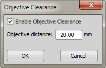
Figure 747.
Optical axis is a little different between two objective lenses on a nosepiece. This function opens the Objective XY Offset dialog where it is possible to define XY offsets between objectives.
 Load
Load This button appears if a Ti2 microscope is connected and enables the user to load offset settings directly from the microscope.
Note
While Ti2 is controlled by NIS-Elements, Ti2 offset settings defined via the Ti2 Assist software are disabled. This is the way to load them and use them within NIS-Elements.
Applies XY offsets between objectives based on the values set in the Objective XY Offset dialog window (see: Devices > Objectives XY Offset Setup).
If there is more than one Z drive connected, this submenu enables you to select the primary one. The following commands are affected by the selection:
The following commands do NOT respect the selection:
(requires: Z Drive)
When the logical device Z drive is present in the system (does not matter which physical device it is a part of), this command appears in the Devices menu.
If you activate it, the mouse wheel will be used for focusing (moving the Z drive) and not for zooming the image while in the live mode. The focusing step can be adjusted by the use of the Devices > Mouse Joystick Setup command from the Devices menu.
Sets the Z-step used for focusing by a mouse wheel. The focusing is done by a mouse wheel when the Devices > Enable Mouse Joystick Z in Live command is ON.
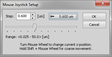
Figure 748.
Indicates the z-step in micrometers. To change it, you can:
Sets the slider to a value optimized for the currently selected objective. If no objective is active, the default value is 5 µm.
Note
Default value is computed as half of Z-Step (AF) - a value defined for each objective. See Calibration > Objectives.
Note
Minimal mouse joystick step has been adjusted according to the connected Z device. For example, Ti Z Drive minimal step is 25 nm, MCL NanoDrive minimal step is 10 nm.
Adjusts settings to be used by the Devices > Fast Auto Focus command.
Note
The functionality is available only with certain microscopes and cameras connected.
Select a way the focusing range is specified and enter the required values.
Select the focus criterion according to the type of experiment.
A criterion suitable for the current light path will be selected automatically.
Uses DIA illumination.
Uses a confocal microscope.
Uses EPI illumination.
.ai-based brightfield criterions intended for a thin layer of cells in a PBS. Unlike the Brightfield criterion, they does not mis-detect scratches for cells. Specific hardware settings are required:
DIA illumination, aperture: 0.02.
DIA illumination, aperture: open (0.15 for 10x objective, 0.24 for 20x objective).
Select a criterion to be used if the Automatic option determines the current modality is brightfield.
Starts automatic focusing according to the settings defined by the Devices > Fast Auto Focus Setup command. It uses a continuous movement of the Z drive and therefore it is usually much faster than the Devices > Auto Focus command.
Note
The functionality is available only with certain microscopes and cameras connected.
Sets the focusing method and parameters. The focus setup window appears. Each time the Devices > Auto Focus command is run, the auto focus method which is currently selected within this window is used. There are the following methods available: Steps in Range and Continuous in Range.
Steps in Range
The Steps in Range method moves the Z drive in steps within a defined range. The Z position with the best focus criterion is used as “focused”.
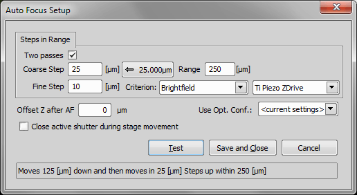
Figure 749.
Select this option to perform auto focus in two steps: Coarse and Fine.
Define the step size (distance between two Z positions) in micrometers. There is a button left of the Range field which indicates a step size recommended for the current objective magnification. Click the button to insert the value to the “step” field.
Define the total distance which the Z drive will use for auto focus.
Defines which focus criterion is used:
This option may be useful in fluorescence applications for the cases where the auto focus algorithm produces offset (the system states it is focused but you would like to focus on some other objects within the image, which are blurry). After performing auto focus, the Z drive will move by the distance defined within this field.
The active shutter will close in times between acquisitions phases. Typically, this option is used to reduce the photo-bleaching effect on live cells.
Select an existing optical configuration.
Press this button to start focusing immediately. If everything works fine, click the button to apply the setting.
Note
When working with low-magnification objectives (4x for example) use higher steps (like 10 microns). For higher magnifying microscopic objectives (for example 40x) use lower steps (like 3 microns). Also, the travel range should be adjusted for each objective. For example the travel range for a 20x objective should be about 100 micrometers. Be sure not to enter higher travel range than half of the working distance of the objective. For explanation, please see the picture.
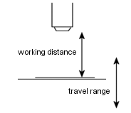
Figure 750.
Continuous in Range (requires Nikon Ni or Ti2-E microscope)
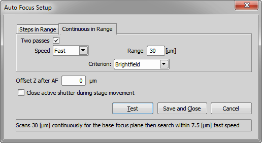
Figure 751.
This method is similar to the Steps in range except that in this case, the step size depends on the camera frame rate. See above for description of the other options.
Select how fast the Z drive will go through the range (fast/slow/normal). Use slow speed for maximum precision of the autofocus.
Note
If the Continuous in range two-pass auto focus fails the reason may be:
Try reducing the auto focus speed to Slow, adjust camera the exposure time, or use the Single pass mode.
Starts automatic focusing according to the settings defined by the Devices > Auto Focus Setup command.
Note
The focusing respects the probe setting. If the probe is not activated, the focusing is done in the full picture. Switch the probe on (for example by the Ctrl+Alt+Shift+P hotkey) to focus only inside the probe area.
Turns the PFS on and finds the offset value so that it corresponds to the current Z-drive position.
Note
The PFS must be off for this command to be enabled.
Define settings to be used when the Devices > Auto PFS Focus command is called.
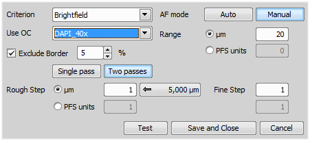
Figure 752.
The settings equal the Devices > Auto Focus Setup command with the difference that you can select between micrometers and PFS units here.
Defines which focus criterion is used:
Automatic focus mode, only the range shall be defined. The system calculates optimal step and whether 1 pass or 2 passes will be performed.
Manual focusing mode enabling further settings. The focusing range and step in the first and second pass can be defined manually.
Select an existing optical configuration.
Define the total distance which the Z drive will use for auto focus either in µm or PFS units.
This function excludes the border of the image and uses only the central part for focus. Width of the excluded border in percent can be set in the edit box.
Define the step size (distance between two Z positions) in µm or PFS units. There is a button on the right which indicates the step size recommended for the current objective magnification. Click the button to insert the value.
performs auto focus in one step. This is a standard auto focus method which can be used.
This method is suitable when you are far out of focus. It is performed in two steps: Coarse and Fine.
Note
If the Continuous in range two-pass auto focus fails the reason may be:
Try reducing the auto focus speed to Slow, adjust camera the exposure time, or use the Single pass mode.
Press this button to test the current settings and start focusing immediately.
Applies the current settings and closes the dialog window.
Closes the dialog window without applying any settings.
This command tries to find the best focused image plane and set the PFS Offset accordingly. It is very similar to the Devices > Auto Focus with the difference that the result of Auto Focus is a Z-position while the result of Auto PFS Focus is the PFS Offset value. However, both commands should lead to a focused image.
This command enables you to compensate systematical focus trends caused by a badly adjusted (not even) stage or by a sloping specimen.
It opens the XYZ Overview control window. See View > Acquisition Controls > XYZ Overview  for more information.
This command performs planar interpolation of points to calculate the focus.
Sets up parameters for automatic scanning. The Define Scanning dialog box appears. This dialog box sets parameters for the Scan command from the menu Devices.
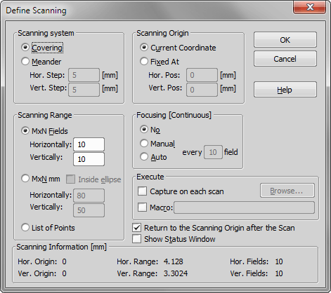
Figure 753.
Type of scanning system.
Areas inside Measurement Frames in scanned fields are touching.
Field increments follow.
Field increment in horizontal dimension.
Field increment in vertical dimension.
Type of scanning range.
Scanning range is MxN fields.
Number of fields in horizontal direction.
Number of fields in vertical direction.
Scanning range is MxN millimeters.
Number of millimeters in horizontal direction.
Number of millimeters in vertical direction.
The scan is performed in the ellipse with MxN bounding rectangle.
Scanning range is defined with currently opened list of points.
Define Scanning Origin.
Scanning Origin will be the current stage position when function Scan is performed.
Specify the absolute position in millimeters.
Horizontal starting position.
Vertical starting position.
Frequency and type of focusing during scanning.
No focus.
Manual focus.
Automatic focus.
Frequency of focusing, valid for manual and auto focus.
Filename of macro executed on every scanned field.
If checked, the stage is moved to the starting position when scanning is finished.
If checked, status dialog informing you about the scanning progress will appear. This dialog also enables you to stop scanning.
See Also
Devices > Scan
Executes scanning accordingly to the parameters set by the Devices > Scanning Setup command. When selecting this command the stage will start scanning and indicate the progress.
Note
If you have specified any macro in the Setup Scanning then it is possible to interrupt the scanning cycle with the Ctrl+Break keys combination.
This command displays the following window, where it is possible to define the list of XY(Z) positions in the same way as if performing a multi-point experiment. See Multi-point Acquisition for more information about using this window. This list of points is shared, so it is used whenever one of the following commands is used:
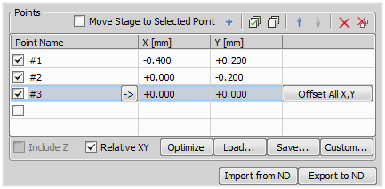
Figure 754.

Some microscopes are equipped with a zoom device. If so, it is always needed to let NIS-Elements know, what the current zoom factor is, otherwise some objective calibrations (made with different zoom setting) would get invalid. If the zoom device is included in the microscope (such as Nikon Ti), the Zoom logical device is included in it and the zoom factor can be set within the Microscope Control Pad window. For other “manual” zoom devices, you should run this command in order to configure it. the following window appears:
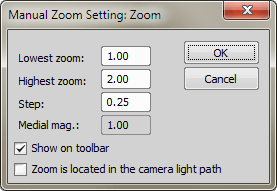
Figure 755.
Usually, this value is 1 or less.
Usually, this value is higher than 1.
Set the smallest zoom change the device is able to perform.
Additional piece of hardware which further extends the abilities of the zoom device can be attached. The extra zoom factor of such device is indicated in this field.
Check the Show on toolbar check box. Two new items, the button and a pull-down menu appear in the NIS-Elements main toolbar. In the pull-down menu, the currently selected zoom factor is indicated. The WT button enables the user to setup the zoom factors and displays the Manual Zoom Setting dialog box.
This option actually tells the system that the zoom device is in use. When selected, objective calibrations are automatically being recalculated according to the currently selected zoom factor.
Note
When creating a calibration, make sure, that the current zoom factor setting on the microscope matches the zoom factor set within the drop-down menu.
(requires: TTL/Analog IO)
This command enables calibration of Calibrated Analog Input signal. The following window appears:
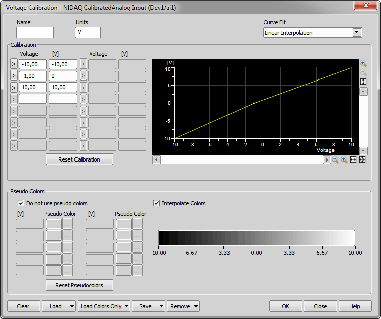
Figure 756.
Displays name of the calibrated values.
Displays units of the calibrated values.
Select which interpolation method fits the best the calibration data.
Enter as many voltage-power pairs as needed to the edit boxes. If the connected device behavior is linear, two pairs are enough. You can also insert the current voltage value by clicking the > button. The calibration curve is displayed on the right side as you type the values in.
Clear all filled values and removes the calibration curve.
Loads a calibration curve from an external file.
Loads pseudo colors scheme from an external file.
Save defined calibration curve to an external file.
Removes selected calibration curve.
(requires: TTL/Analog IO)
This command enables calibration of Calibrated Analog Output signal. Following window appears:
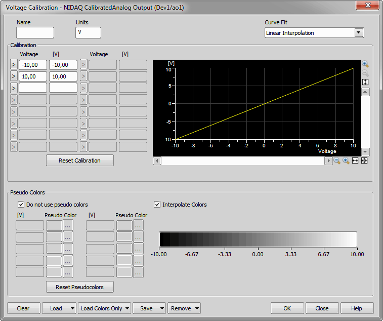
Figure 757.
Displays name of the calibrated values.
Displays units of the calibrated values.
Select which interpolation method fits the best the calibration data.
Enter as many voltage-power pairs as needed to the edit boxes. If the connected device behavior is linear, two pairs are enough. You can also insert the current voltage value by clicking the > button. The calibration curve is displayed on the right side as you type the values in.
Clear all filled values and removes the calibration curve.
Loads a calibration curve from an external file.
Loads pseudo colors scheme from an external file.
Save defined calibration curve to an external file.
Removes selected calibration curve.
(requires: Wavelength Switcher)
This command opens a window which enables you to create a calibration curve (map voltage values to laser power values) of the selected laser line.
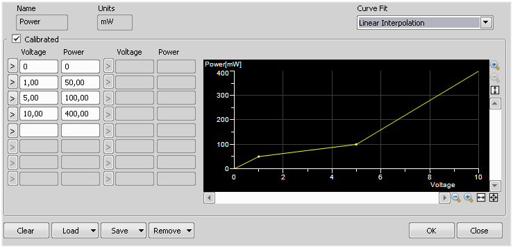
Figure 758.
Displays the name of the calibrated values.
Displays the units used for calibration.
Select an interpolation method which corresponds with your calibrated data.
Once checked, the laser is switched to the calibrated output mode and calibration table editing is enabled. Enter as many voltage-power pairs as needed into the edit boxes. If the connected device behavior is linear, two pairs are enough. You can use the > button to insert current voltage value. The calibration curve is displayed on the right side as you type new values in. If unchecked, calibration settings are not applied.
Clears all calibration values and removes the calibration curve.
Loads the calibration settings from an XML file.
Saves your custom calibration to an external file.
Removes the calibration curve selected.
This command appears in the Devices menu when at least one shutter or filter changer is installed. The following control window appears. There you can open and close the shutters by clicking the shutter icon, and change the filters by selecting them from a combo box. More information in this section View > Acquisition Controls > Filters, Shutters and Switchers 
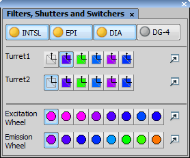
Figure 759.
Displays a window where you can visually compare fluorescent probes and the optical filters characteristics. The very same window is described in Calibration > New Optical Configuration for Fluorescent Probe command description.
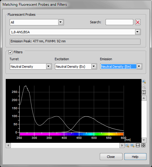
Figure 760.
See Also
Calibration > New Optical Configuration for Fluorescent Probe

Displays the control pad of the current microscope.
Note
this command is only displayed when a microscope is connected to the system.
See also Connecting a Device to NIS-Elements, Microscopes.