Create a new text file for each probe. The file extension is not required.
Insert the tabbed spectra description (see below).
Save the file to the Fluorescent Probes folder.

This command is used to create a new optical configuration. It runs the optical configuration wizard. See Optical Configurations for more information.
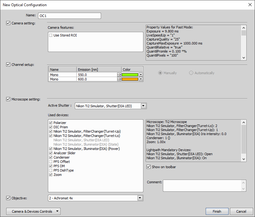
Figure 561.
Displays editable name of the selected optical configuration.
Check this item to include the current camera settings to the new optical configuration.
If you want to include the camera ROI settings, select this option. Status of the camera ROI (ON/OFF) and its size will be set when switching to this configuration.
These settings determine how channels of newly captured images will be named and what color will be assigned to them. The available properties depends on the current camera setup (color/mono). In the mono camera mode, you can either assign the name, the emission length and color to the channel Manually, or leave this task to NIS-Elements (the Automatically option). In such case, information of the light path (emission wavelength) will be used to determine the channel name and color.
Check this item to include the current logical devices to the new optical configuration.
Select a shutter from a list of all available shutters in the pull down menu. If you are running the NIS-Elements in a Multi Camera mode then second Active Shutter item appears.
Check all the available logical devices you would like to use.
Check this item to include the objective (nosepiece position) in the configuration. Select which nosepiece position will be assigned from the drop-down menu.
Press this button to create new optical configuration and close the dialog.
Press this button to close the dialog without creating optical configuration.
This command is oriented on fluorescence microscopy and creates a standard optical configuration. Optical filters and fluorescent probes characteristics are displayed within the window:
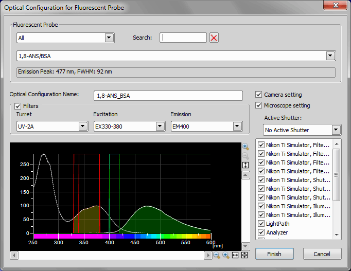
Figure 562.
The pull-down menus of this section serves for selecting the fluorescent probe(s) which you prepare the optical configuration for. There are two pull-down menus - probe categories and the list of all probes. Selecting a category restricts the list of probes. You can also use the text Search box to quickly search for the desired probe by its name.
Characteristics of the selected probe appears in the space below the menus and a graph of its emission/excitation efficiency is displayed.
When you select a probe, the Opt. Conf. Name is suggested automatically. It can be edited. On the right side, there you can select which hardware settings will be included in the optical configuration (Optical Configurations).
Select the Filters check box to include filter changers settings in the optical configuration. The Turret, Excitation, and Emission pull-down menus become active. When a filter is selected, its characteristics (raising edge, falling edge) are indicated in the graph.
When you capture a channel using the optical configuration created by this window, a color is assigned to it automatically. However, its value is computed from the emission characteristics of the probe used. Therefore, the channel color may differ from the color you see in live.
To extend the list of predefined fluorescent probes, spectral description of additional probes should be placed to the following folder:
/Documents and Settings/All Users/Application Data/Laboratory Imaging/NIS-Elements /Fluorescent Probes/
The name of the text file (with the extension omitted) will be used for the probe name. If the probe name should contain the “/” symbol, substitute it with “#” in the filename. It will be replaced automatically. Example: “6-JOE#pH 9.0.txt” will appear as “6-JOE/pH 9.0” in the list.
The text file should contain tabbed spectra - values should be ordered in four columns separated by commas: excitation wavelength, excitation efficiency (0 to 100), emission wavelength, emission efficiency.
wl,ex,wl,em,bcecf pH 9.0
350,2.692229112,490,1.133401306
351,2.574480095,491,1.305799109
352,2.363020877,492,1.654297369
353,2.142321069,493,2.050701739
354,2.021000726,494,2.521964011
355,1.870400784,495,3.090271618
356,1.761319669,496,3.838160674
357,1.651571787,497,4.709683551
358,1.575326078,498,5.722835683
359,1.515644513,499,6.948201622
360,1.460545109,500,8.564930898
361,1.403794606,501,10.24974485
362,1.397394846,502,12.1573046
This is a standard format provided e.g. by Invitrogen - Molecular Probes.

Optical configurations command enables you to create and manage optical configurations (settings of your whole optical path - objective calibration and camera or microscope settings). The following window appears:
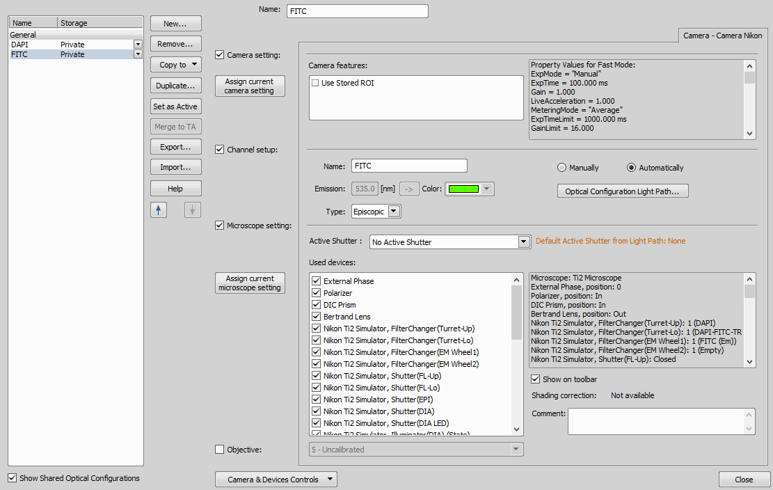
Figure 563.
Main Options
Displays a list of all optical configurations. You see editable name of the optical configuration in the left column. You can change the status (Shared/Private) of an optical configuration in the right column. When you need to manage more optical configurations, you can select them and change their properties, or remove them at once.
Unchecking this item hides all shared optical configurations.
Creates a new optical configuration. This button opens the Optical Configuration Wizard. See Creating New Optical Configuration for more information.
Removes the selected optical configuration.
Renames the selected optical configuration.
Copies selected optical configuration to an already existing configuration. The original configuration is overwritten by the copied one.
Creates a duplicate optical configuration. This button opens the Duplicating optical configuration. Enter a name for the new optical configuration in the window which appears.
Sets selected optical configuration as active.
(requires: RT Acquisition)
Select two or more configurations holding Ctrl and click this button to create a new one. The software creates a triggered acquisition sequence automatically and saves it to the new optical configuration. This button provides a simple way to create a triggered acquisition sequence. See Creating Optical Configurations for Multi-channel Triggered Acquisition.
Backs up the optical configuration settings. The settings is saved in a *.xml file. In a dialog which appears, define the name and location of the saved file and check which optical configurations will be included in the exported .xml file.
Opens a previously saved optical configuration settings. The settings can be opened from a *.xml file. When you try to import an optical configuration with an already existing name, you will be prompted to choose whether the imported optical configuration replaces the existing colliding configuration, or is not imported, or is imported and renamed.
Opens this help page.
Move the selected optical configuration one position up or down using these arrow buttons.
Shows a list of control windows (Camera settings, Microscope pad, filters and shutters, etc).
Optical Configuration Details
The following details of the selected optical configuration may be set in the right portion of the window.
Displays editable name of the selected optical configuration.
This item appears only in multi camera mode. It defines which camera settings are saved in the optical configuration.
Check this item to include the camera settings to the currently selected optical configuration. If you press the Assign current camera setting button, the current camera setting will be assigned to the selected optical configuration. Overview the properties of a camera which is assigned to the selected optical configuration in the field on the right side.
Check this item to include the channel setup to the currently selected optical configuration. These settings determine how channels of newly captured images are named and what color is assigned to them. You can choose type of illumination: episcopic and diascopic.
If you are using a monochromatic camera, you also see information about channel emission wavelength and color. You can set the channel setup manually or automatically. During manual setup, you can change the emission wavelength or color.
Check this item to include the microscope settings to the currently selected optical configuration.
The Active Shutter option determines which shutter is assigned to the optical configuration. Select a shutter from a list of all available shutters in the pull down menu. If you are running the NIS-Elements in a Multi Camera mode then second Active Shutter item appears.
If you press the Assign current microscope setting button, the current microscope setting will be assigned to the selected optical configuration. Overview the properties of a microscope which is assigned to the selected optical configuration in the field in the middle of the window. On the right side of the window is a list of all logical Used devices which microscope use and which can be subsequently added to the optical configuration. Add or remove a devices by checking or ticking off the check boxes.
Check this item to include an objective to the currently selected optical configuration. Select an objective from a list in the pull down menu.
Check this item to add a shortcut to the selected optical configuration into the main toolbar.
Displays whether a shading correction image is saved in selected optical configuration.
Add an arbitrary comment.
A list of often used objectives can be created within the Objectives window. For each objective, the objective name, position in the changer, storage status and the calibration are displayed. A Calculator  icon next to the calibration value indicates that the calibration has been calculated from objective properties. If the icon is missing, it means the calibration has been performed manually. Use the following buttons on the right side to manage the objectives.
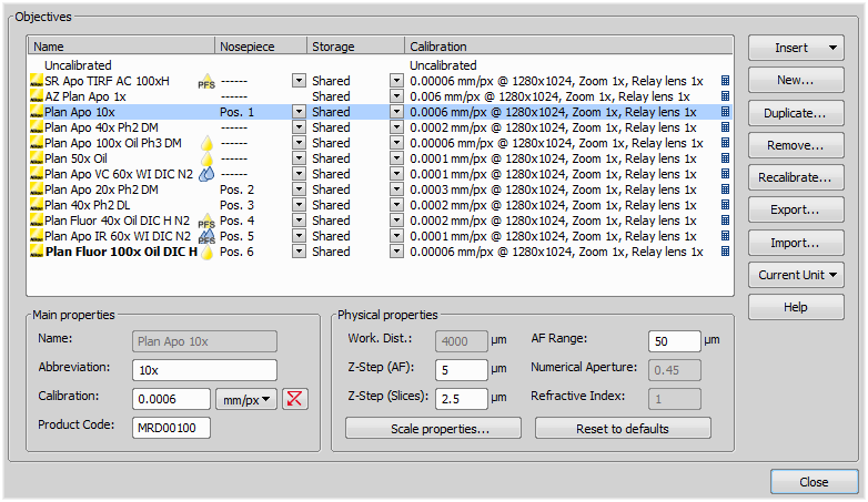
Figure 564.
List of Objectives
All objectives are listed in the main part of the window. You see name of the objective in the left column. Change the status (Shared / Private) of an objective in the middle portion of the window. The last column shows calibration of the objective.
Click the button and select one of the predefined objectives which can be assigned to a currently connected microscope. The list is ordered by magnification. If no microscope is connected then all objectives are displayed.
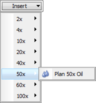
Figure 565.
Icons by objective names indicate the objective type. Combinations of the following symbols can appear:
Dry

Water immersion

Oil immersion

Silicon oil immersion

PFS

PFS with support for glass/plastic dish

Water immersion dispenser (WID)
Custom objectives can be added to the database via an INI file. See Adding Objectives to Objective Database.
Opens Create objective window. Enter a new objective name and confirm it by clicking the button. Proceed to objective calibration. See Objective Calibration for further information about objective calibration.
If zoom is used, the objective calibration must be re-calculated accordingly. Use this button to duplicate selected objective. Enter a name and zoom factor of the duplicated objective in the window that appears:
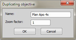
Figure 566.
Removes selected objective.
Backs up the objectives settings. The settings is saved in a *.xml file. In the windows that appears, define the destination file name and check which objectives will be included in the exported xml file.
Enables the complete list of objectives to an XML file. The standard Save As window appears. Select which objectives will be included in the exported XML file on the left side of the window.
Opens the previously saved objectives settings. The settings can be opened from a *.xml file.
Imports a list of objectives from an external XML file previously created by the Export button.
Note
When you try to import an objective which is already in the system (has the same name), you will be prompted to choose whether the imported objective replaces the existing colliding objective or will not be imported or will be imported and renamed.
NIS-Elements supports the following length units: nanometers (nm), micrometers (µm), millimeters (mm), centimeters (cm), decimeters (dm), meters (m), mils (mil), and inches (inch). Select unit for calibration of all objectives.
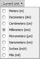
Figure 567.
Main Properties
Displays name of the currently selected objective. You can not change the names of objectives from Nikon database.
Edit the abbreviation of a selected objective.
Edit the calibration of a selected objective. Press the unit button to change the units used for calibration.
Displays the product code.
Physical Properties
Displays working distance of the currently selected objective. You can not change the working distance of objectives from Nikon database.
Edit the AF Range of a selected objective.
Edit the Z-step (AF) of a selected objective.
Displays numerical aperture of the objective. You can not change the numerical aperture of objectives from Nikon database.
Edit the Z-step (slices) of a selected objective.
Displays the refractive index value of the objective. You can not change the refractive index of objectives from Nikon database.
Opens the Scale Properties window. See View > Layers Properties > Scale Properties for further information.
This button enables you to load the default values of the objective Physical Properties.
This command starts the calibration procedure of the current objective. The following dialog appears:
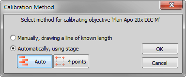
Figure 568.
Select a method for calibrating the objective.
Manual calibration is done by drawing a line of known length to the image. You should have some kind of calibration slide or a ruler placed in the scene.
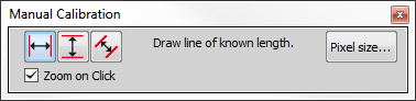
Figure 569.
Choose one of the three modes: horizontal, vertical and parallel lines. Click into the image to place the first line, then the second line appears under your mouse cursor. Place the line by clicking again to define the distance. Select the Zoom on Click option to automatically zoom-in when positioning the line. This helps to precisely define the line position. Pixel size can also be defined if needed. Once both lines are placed, the following window appears:
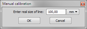
Figure 570.
Enter the known length of the drawn distance, make sure the units are correctly selected and click .
(requires: Stage)
If you choose the automatic method, the application will guide you through the calibration process. The Auto method is fully automated. The 4 points method needs your cooperation. Move the stage to the marked points and when you reach the position, click . The calibration will be calculated automatically afterwards.
This command recalibrates an image, which was already calibrated.
Figure 571.
This is done by drawing the line of known length. Edit the pixel size first when needed:
Figure 572.
There are three modes: horizontal, vertical and parallel lines. Click into image to place first line, then second line appears on your mouse cursor. Place this line and the following dialog box appears:
Figure 573.
Enter a defined length in real units and press OK.