Install NIS-Elements. If an NIDAQ board is needed in your setup (check the Wiring Overview chapter), select one of the following options within the Devices > National Instruments section of the installation wizard:
driver for use with all I/O functions
legacy drivers for use with Piezo Z
See Device Manager Settings for details about settings of the NIDAQ board within NIS-Elements.
No special software settings are necessary. The exposure signal is being generated on the I/O connector automatically.
Run the Devices > Device Manager
 command.
Reveal the context menu over the NIDAQ device and click .
In the NIDAQ Configuration window, select Illumination Device from the right column and click (add it from the left column if there is no Illumination Device).
The following window appears. Select to which lines of the break-out box the camera and MLC 400 are connected.
Run the Devices > Device Manager
command.Reveal the context menu over the NIDAQ device and click .
In the NIDAQ Configuration window, select Piezo Z from the right column and click (add it from the left column if there is no Piezo Z).
The following window appears:
For applications using an NIDAQ board (see Wiring Overview), run the Devices > Device Manager command and Add the “NIDAQ” device. The following window appears:
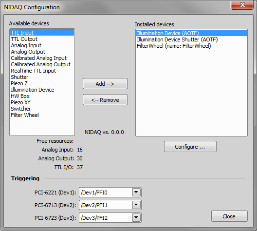
Figure 494.
All devices which are connected to the NIDAQ card should be added to the list of Installed devices and configured properly (see the description below). Apart from that, it is important to set the Triggering line correctly. There is a list of all NIDAQ cards found in your PC at the bottom of the window. For each card, select the PFI input connector to which the TTL triggering signal is connected.
No special settings are necessary for these devices. NIS-Elements uploads the sequence of wavelengths to the device controller via the RS232/USB interface before the triggered acquisition is started.
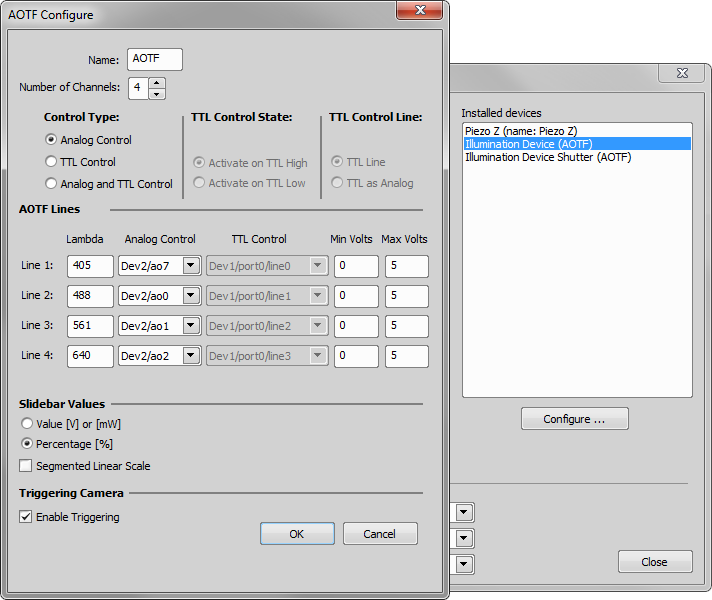
Figure 495.
Note
It is important that the PFI line and the output lines are attached and assigned to one NIDAQ board.
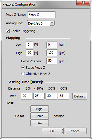
Figure 496.
Select the Analog Line to which the device is physically connected and select the Enable Triggering check box. Set mapping between voltage and position and select the type of your Piezo drive to let the system know its orientation: Stage Piezo Z or Objective Piezo Z.
There is always a delay between the moment the Z drive receives the signal to move and the moment it achieves the target position. By defining the Settling Time, you are telling the software to postpone the capture so images are not taken while the Z drive is moving. The actual settling time is related to travel distance:
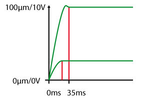
Figure 497. Optimal settling times for different travel distances
You can optimize behavior of your piezo Z drive by setting different settling times for different travel distances. Travel distance is given as a percentage of the entire Z range.
Custom-named shutters can be controlled by TTL or Analog signals. For this purpose, you can set-up open and close parameters, and the state of the shutter which will be set upon NIS-Elements startup or shutdown.
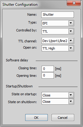
Figure 498.
In either Acquire > Capture Z-Series > Capture Automatically or Applications > 4D > Define/Run ND Acquisition window, select the Triggered NIDAQ Piezo Z from the Z Device pull-down menu. Define Z stack parameters and press the button.
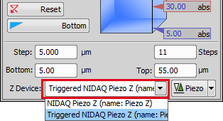
Figure 499.
Run View > Acquisition Controls > Triggered Acquisition  . The following window appears:
Note
The window layout and the options-set differs depending on which Multi-Excitation Device is selected.
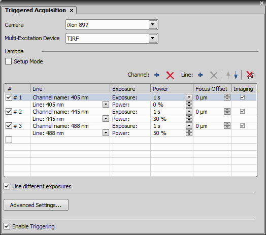
Figure 500. Example of the Triggered Acquisition Window
Common Options
Define which camera is used for acquisition. All currently connected (monochromatic) cameras are listed.
Define which device is used for acquisition. All connected multi-laser illumination listed.
Select the Enable Triggering option to enable the Setup Mode. Select the box and radio buttons appear in the # column. Select a channel to test its settings (live image of this channel will run).
 Add New (Channel/Line)
 This button adds rows to the list of channels. New channels are created at the end of the table. New Lines are inserted to the currently selected channel.
 Remove (Channel/Line)
 This button removes the selected row (line or a channel).

 Move Up/Down
 Moves the selected row up or down.
 Delete All
 Deletes all lines in the definition table.
A check box and an automatic channel number appear in this column. Deselect the check box to omit the channel from acquisition.
Editable channel name. It inherits the wavelength number of the inserted line by default.
Select one of the available lines to be used with the channel. A line may specify a laser or other output signal (e.g. analog output).
Defines power to be generated by the line. Percentage of the total power (%) for lasers or voltage of the analog output is used.
Specify exposure time of the corresponding channel.
Select this box to turn the triggering ON. When you run the Live Image - a multichannel image shall appear on screen.
Special Options
If enabled in the Advanced Settings... window, it specifies Z-offset for each channel.
If enabled in the Advanced Settings... window, imaging and non-imaging channels can be distinguished. A non-imaging channel performs some action without capturing an image.
This option turns on/off the possibility to select different exposures for each channel. It is supported only by Andor and Photometrics Evolve 512 cameras.
In most cases, the Exposure option should be turned on.
Note
Use the Readout option only when using legacy cables + Sutter DG-4.
This option is available only if HW Box and DG4 are connected. If it is selected, then the shutter is opened only during exposure and is closed during readout.
Advanced Settings...
The following window appears when the button is pressed:
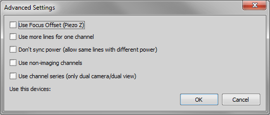
Figure 501.
If a piezo Z is available, this option adds a column to the channels setup. The offset value may be specified for each channel separately.
Enables the user to add more lines (lasers/output signals) to a single channel.
If one line of an (analog-controlled) illumination device is used in two or more channels, its power is synchronized by default. So if you change the setting in one channel, the corresponding lines in other channels change as well. This behavior can be disabled by selecting this option.
Apart from capturing a channel image, the triggering signal can start other actions - for example moving a piezo Z drive. Such an action is called a non-imaging channel because the action is performed but no image is captured.
If you check this option, the number of camera channels and excitation channels has to be the same. The first excitation channel is used with the first camera channel, the second with the second, etc.
Output lines and devices which can be used during triggered acquisition are listed in this place. Select the check-boxes of the devices which should be listed in the main Triggered Acquisition window.
Perform both of the above procedures and then run the acquisition.
There are two ways to create an optical configuration containing a triggered-acquisition recipe.
Using the Triggered Acquisition Panel
Run the View > Acquisition Controls > Triggered Acquisition
command to display the panel.Select devices for triggering and define the acquisition channels (see above). Select the Enable Triggering check box.
Run Calibration > New Optical Configuration
 and select to include Camera setting in the configuration.
Using the Optical Configurations Window
Run the Calibration > Optical Configurations
 command.
Create one optical configuration for each channel. Make sure the Camera setting and Microscope setting options are selected to ensure that settings of the camera and the triggered device are included.
Caution
The Enable Triggering check box in the Triggered Acquisition window must not be selected.
Caution
If the configurations contain also settings of devices which cannot be triggered (e.g. certain filter wheel models), the acquisition sequence will be created anyway, but the state of the filter wheel defined in the first optical configuration will be used throughout the whole sequence.
Select all optical configurations which are intended to compose the triggered acquisition sequence (hold the Ctrl key).
Click the Merge to TA button to create the optical configuration.
This special acquisition mode can accelerate all experiments within NIS-Elements using the NIDAQ board.
Connect the camera exposure/fire TTL line to the NIDAQ TTL input (or analog input).
Go to Devices > Device Manager
and the “NIDAQ” device.The NIDAQ Configuration window opens.
In the Available devices area, select “Exposure Signal TTL In” and click .
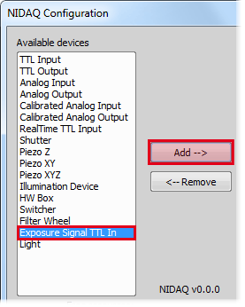
Figure 502.
Confirm your Configuration settings.
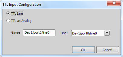
Figure 503.
To enable/disable the speed up function, reveal the context menu over the NIDAQ device and click Set Components... and check/uncheck the logical device.
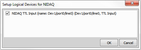
Figure 504.
Once the speed up is enabled a notification is displayed within the ND Acquisition control panel.
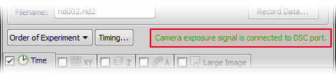
Figure 505.
Note
NIDAQ Exposure Signal TTL In should not be used with Ti-E or Ti2-E microscopes. It is designed for microscopes which cannot use the Ti recipe.