Connect the triggering cable to the connector of your camera which transmits the triggering TTL signal. The other end of the cable which carries the Exposure TTL signal must be connected either directly to the triggered device (or its controller) or to a PFI connector of an NIDAQ card - in case such a card is used.
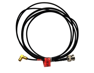
Figure 463. Andor iXon/Luca triggering cable
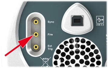
Figure 464. Luca Fire connector
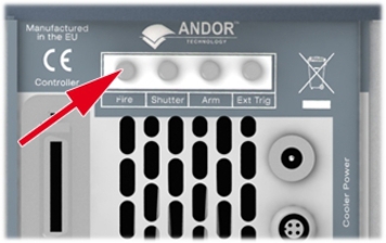
Figure 465. iXon Fire connector
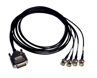
Figure 466. Andor Clara triggering cable
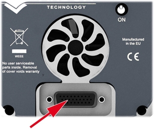
Figure 467. I/O connector, Fire
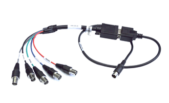
Figure 468. CoolSNAP MYO / KINO triggering cable
Note
Obtain the cable from Photometrics part #: CBL-IO-HR10-F-BNC
Use the BNC cable labeled “Expose Out”.
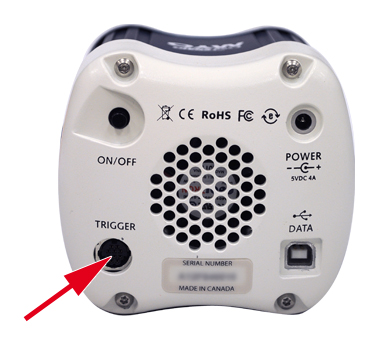
Figure 469. TRIGGER connector
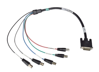
Figure 470. CoolSNAP HQ2 triggering cable
Note
Obtain the cable from Photometrics part #: 37-107-002
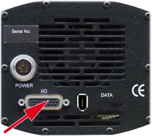
Figure 471. I/O connector, “Exposure” BNC
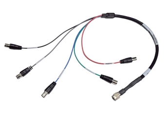
Figure 472. QuantEM:512SC triggering cable
Note
Obtain the cable from Photometrics part #: 37-513-003
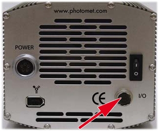
Figure 473. I/O connector, Exposure BNC
Connect the triggering cable to the Timing I/O connector of the camera. The Exposure signal goes to the branch labeled Signal 1.
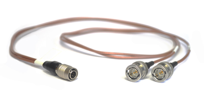
Figure 474. Exposure signal goes to “Signal 1”
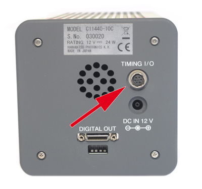
Figure 475. Timing I/O connector
Connect the cable to the Timing 1 connector on the camera body.
Figure 476. ORCA Flash4.0 Triggering Cable
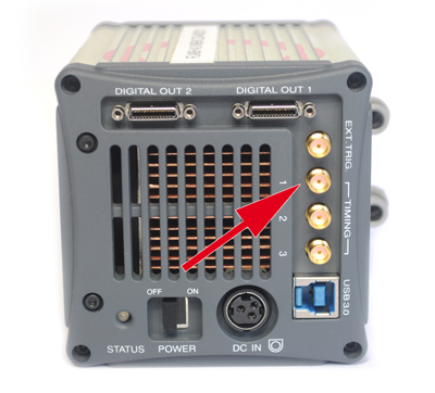
Figure 477. Timing 1 connector
Use standard BNC-to-BNC cable to connect the device to be triggered to the Timing I/O 2 connector.
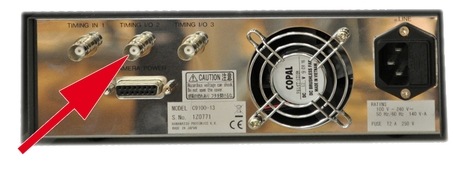
Figure 478. Timing I/O 2 connector
Use DG-4 shutter HW box: Plug the In connector to the Exposure signal from the camera, the Out connector to the Strobe connector on the DG-4 body, and the USB connector to the computer.
Note
The purpose of the box is to avoid bleaching a sample during camera readout in multi excitation. It is the product of Laboratory Imaging and can be ordered at sales@lim.cz, LIM product code LA_TRGSHUT.
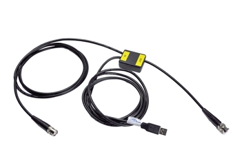
Figure 479. DG4 Shutter HW box
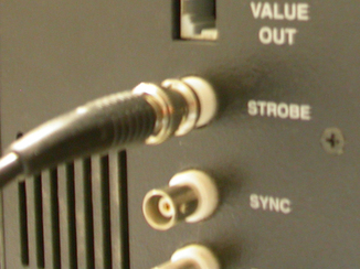
Figure 480. The Strobe connector of DG4
Note
If you do not use the HW box and connect the Exposure signal to the Strobe connector (via a BNC-to-BNC cable), the specimen will be illuminated for the whole time of the experiment (even during the readout phase).
The 15-pin D-type connector of the break-out box socket is fitted to the back of the Main Unit. Connect the Exposure signal from the camera to the Sync In connector of the pE-x break-out box.
Note
Purchase “break-out box” (product code #244-10000) from CoolLED.
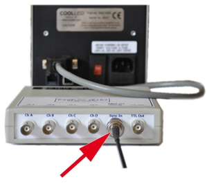
Figure 481. CoolLED pE-x break-out box
Connect the Exposure signal from the camera to the thin branch of the Nikon MXA22104 cable.
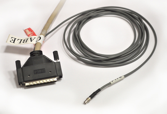
Figure 482. Nikon MXA22104 cable
Figure 483. The back of LU4A
A suitable NI break-out box connected via NIDAQ PCI card will be needed. The box must contain at least one PFI input (capable of receiving the TTL triggering signal) and four analog outputs to control the lasers.
Connect the camera Exposure signal to the PFI connector of the break-out box and also select four analogue outputs and connect them to the Analog Input connectors of MLC 400. In the next step, you will assign the connected analog outputs to the Illumination Device within the NIDAQ configuration window.
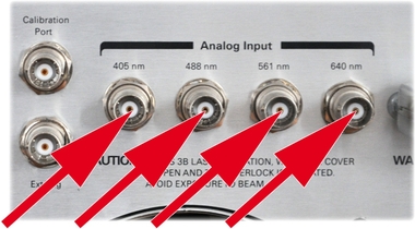
Figure 484. Analog Input connectors of MLC 400
The triggered Piezo Z always requires an NIDAQ board with at least one analog output to control the piezo Z controller and one PFI input which accepts the TTL exposure signal from the camera.
Use the Input connector of the NanoScanZ/Nano-Drive controllers.
Use the Control In connector of the E-665 controller.
Use the 68pin-2BNC Real Time Acquisition Cable (to be purchased at sales@lim.cz), formerly sold under the code LA_RTPZMXAC) to establish the connection between camera, NIDAQ board and the Piezo Z controller. Correct software options must be set within the Piezo Z configuration: input pin - PFI 5, output pin - AO 0.
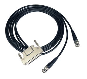
Figure 485. 68pin-2BNC Real Time Acquisition Cable
Note
A suitable break-out box can be used instead of the Figure 485, “68pin-2BNC Real Time Acquisition Cable”. The box must contain at least one PFI input (capable of receiving the TTL triggering signal) and one analog output to trigger the Z controller.
Connect the 68pin connector to the NI DAQ PCI board (PCI 6711, PCI 6713, PCI 6733). Connect the Camera end of the cable to the Exposure output signal of the camera, and the remaining end of the cable to the piezo Z controller.
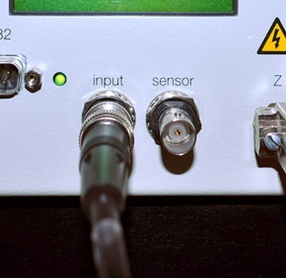
Figure 486. The Input connector of Prior NanoScanZ controller
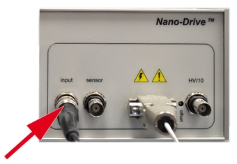
Figure 487. The Input connector of MCL NanoDrive controller
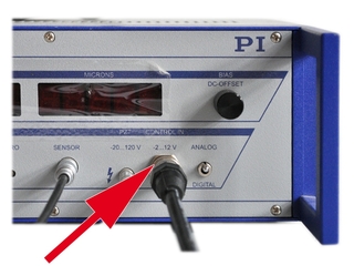
Figure 488. The Control In connector of PI E-665 controller
Multi-excitation (wavelength switcher + camera)
Connect the camera with DG-4 by the triggering cable. It is suggested to buy also the Figure 479, “DG4 Shutter HW box”, but this is optional
Connect the camera with Figure 481, “CoolLED pE-x break-out box” by the triggering cable. The Figure 481, “CoolLED pE-x break-out box” is connected to the CoolLED pE-x controller.
Connect the camera with LU4A by Nikon MXA22104 cable.
Connect the camera with NIDAQ break-out box via PFI (which is connected to a NIDAQ board, e.g. PCI 6711).
Z Stack (piezo Z + camera)
An NIDAQ board and the Figure 485, “68pin-2BNC Real Time Acquisition Cable” is required. The Exposure signal leads to the NIDAQ board. The NIDAQ board triggers the Piezo Z controller.
Multi-excitation + Z stack (wavelength switcher + piezo Z + camera)
This combination requires an NIDAQ board + a break-out box. The beak-out box serves as a hub accepting the input signal from camera and distributing output signals to the wavelength switcher and the piezo Z controller.
This combination requires the Figure 485, “68pin-2BNC Real Time Acquisition Cable”. The camera signal is branched by a BNC “T” piece, one branch leading to the wavelength switcher, the othe leading to NIDAQ board.
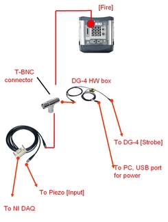
Figure 489. Andor Ixon, DG-4, Piezo Z, HW Box, RT Acquisition CableNote
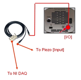
Figure 490. Photometrics QuantEM:512SC, Piezo Z, RT Acquisition CableNote
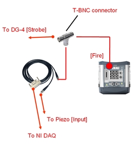
Figure 491. Andor Ixon, DG-4, Piezo Z, RT Acquisition CableNote
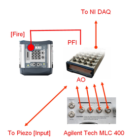
Figure 492. Andor Ixon, Piezo Z, MLC 400 laser combiner
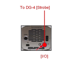
Figure 493. Photometrics QuantEM:512SC, DG-4
Note
A suitable break-out box can be used instead of the Figure 485, “68pin-2BNC Real Time Acquisition Cable”.