

 Define Z-Stack
 This task defines parameters required for capturing a Z-Stack (a sequence of images each having a different focal plane). Please see the Z-series Acquisition chapter for details about the Z-stack setup. Create all-in-focus images or 3D models regardless of your sample and depth of field parameters. | Requires: Device: Stage Z |
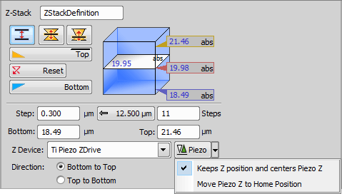
Figure 1313. Defined by top bottom mode
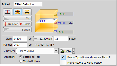
Figure 1314. Symmetric mode defined by range
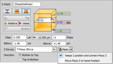
Figure 1315. Asymmetric mode defined by range
Name of your Z-Stack > Define Z-Stack task.
This mode defines the Z-stack using two parallel planes ( ![]() Top and
Top and ![]() Bottom).
Bottom).
Required values: top position, bottom position, step size or number of steps.
This mode defines the Z-stack by its center (Home) position and the same range above and below the Home plane.
Required value: range.
This mode defines the Z-stack by a center (Home) position and a custom range above and below the Home plane.
Required values: above position, below position.
Sets the top Z position.
 Reset
Reset Discards the Top, Home, and Bottom position settings.
Changes the Home (absolute Z) position to Relative (current Z position deducted prior to the actual acquisition).
In the Symmetric / Asymmetric mode defined by range this button sets the position in the middle of your range.
Sets the bottom Z position.
Define the range of a single step.
Click this button to use the recommended step size.
Insert the number of steps you want to acquire.
Set the bottom Z position manually.
Set the top Z position manually.
Choose a Z device used for Z-stack acquisition.
Specifies the role of the Piezo Z drive.
Enter the range of the final Z-stack (in-focus portion of your sample).
Set the bottom position of the Z-Stack manually.
Set the top position of the Z-Stack manually.
Sets the Z axis direction in which the stage will move during acquisition.
 Z-Stack Bottom and Top
 Defines a Z-Stack simply by its top and bottom positions and step. Use the microscope joystick to find the bottom of the inspected cell, click | Requires: Device: Stage Z |
Sets the top Z position.
Reset Discards the Top and Bottom position settings.
Sets the bottom Z position.
Selects the Z-Drive device connected to NIS-Elements.
Defines the range of a single step.
Click this button to use the recommended step size.
 Z-Stack Piezo from Bottom
 Defines a Z-Stack to be acquired from the bottom position to the top using just the Piezo Z drive. Find the bottom of a cell and capture a Z-Stack with the full range of the Piezo Z drive. See also Z-Stack > | Requires: Device: Stage Z |
Name of the task.
Defines the size of the Z-Stack from the bottom to the top. Check Maximum to use the maximum possible distance.
Defines the range of a single step.
Click this button to use the recommended step size.
Displays information about the number of defined steps.
 Z-Stack by Expression
 Defines a Z-Stack using absolute coordinates or variables available in NIS-Elements. Use the button to insert variables into the particular edit box. Use this task when you need to define a Z-Stack with absolute Z positions inserted from variables. | Requires: Device: Stage Z |
Name of the task.
Absolute Z position where the Z-Stack will start.
Absolute Z position where the Z-Stack will end.
Defines the range of a single step.
Selects the preferred Z-Drive device connected to NIS-Elements.
Global Z Coordinates Use Case
In this following example with an inverted microscope, the stage Piezo Z moves against the direction of the microscope Z-drive and the global coordinates are subtracted. To capture a Z stack for global Z coordinates 10 to 50, the microscope Z-Drive goes to 110 and the Stage Piezo Z goes to 100 (global Z coordinate is 110-100 = 10). Then the Stage Piezo Z moves from 100 to 60 so the final global coordinate is 110-60 = 50.
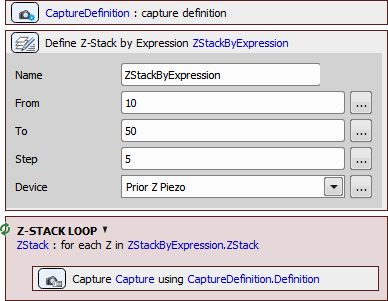
Figure 1316. Jobs definition.
The drawings below show how the global Z value is calculated for different types of Z-devices on different microscopes.
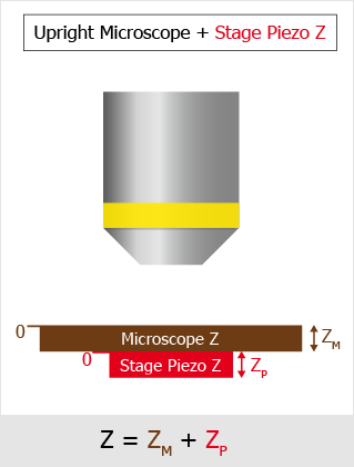
Figure 1317. Upright Microscope with Stage Piezo Z.
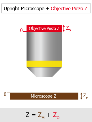
Figure 1318. Upright Microscope with Objective Piezo Z.
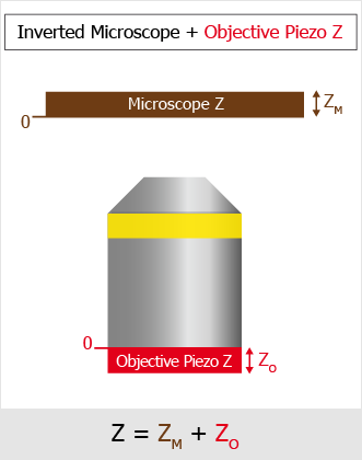
Figure 1319. Inverted Microscope with Objective Piezo Z.
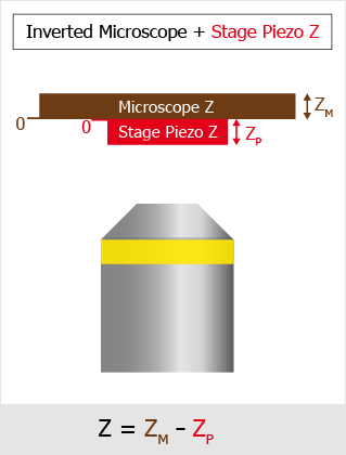
Figure 1320. Inverted Microscope with Stage Piezo Z.
 Z-Stack Loop
 Repeats the contained tasks for each Z position of the selected Z Stack. This task can be used inside any other loop (time-lapse, point set) with Acquisition > | Requires: Device: Stage Z |
 Capture
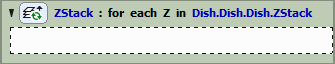
Figure 1321.
 Assign Z-Stack to Point/Well/ND Acquisition
 Every XY position (well, row of wells, column of wells) can have unique Z stack parameters after using this task. Scan a wider Z stack over the wells selected by the analysis. | Requires: Task: Z-Stack > Device: Stage Z |
 ND Acquisition
 Loop over Points
 Loop over Wells
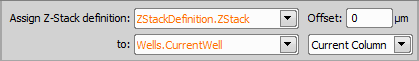
Figure 1322.
Select your Z-Stack definition for the assignment.
Add an optional Z offset on top of the Z-Stack definition.
Select to which the Z-Stack definition will be assigned. If a second combo box appears (e.g. when using well plates) - specify your selection.
 Move to Z-Stack home
 Moves the Z drive to the home position of the selected Z stack definition. When capturing multi-channel Z-stacks, not all the channels are required to contain the Z dimension. These are usually captured in the home (center) position. | Requires: Device: Stage Z |

Figure 1323.
Choose your Z-stack definition from your current job.
Moves the Piezo Z device to the position selected in the Position drop-down menu and compensates the second Z-device to stay on the same Z plane as before. Find the bottom of a cell, reset the Piezo Z bottom position and capture a Z-Stack of the cell using the full range of the Piezo Z drive. | Requires: Device: Stage Z |
Name of the task.
Select the position to which the Piezo Z drive moves. The second Z drive compensates for this movement to stay on the same plane. If the Custom option is selected, an exact Z position can be entered into the field. Range displays the possible Z values falling into the current range of the device.