(requires: Automatic Measurement)

Select the First Layer and the Second Layer from the combo boxes. Binary operations will be performed between these two layers.
Select the logical operation to be performed. You can also select the Preview check box to view the result of the operation in the image window.
Now choose where the result will appear in the Insert Result into area. You can select to overwrite the data in the first or second layer with the data of the result or to create a new layer containing the result. If so, type the name of the new layer in the edit box.
Click to confirm the action.

(requires: Automatic Measurement)(requires: Automatic Measurement)
Note
If you are running NIS-Elements with Local Options (Step 2), please see Define Threshold for the appropriate dialog description.
Thresholds the image and creates a binary layer. Please see Thresholding.
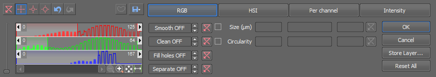
Figure 479.
You can create multiple binary layers within one document. Use the View > Analysis Controls > Binary Layers  control window to manage all binary layers at once.
This button opens a dialog window, which saves the currently thresholded binary as a new layer. Enter Name of the new layer. Set it as visible or not, and specify its color.
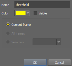
Figure 480.
(requires: Local Option)
Thresholds the image and creates a binary layer. Please see Thresholding.
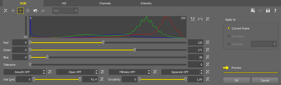
Figure 481.


 Picking tools
 Select a picking tool and click on objects in the image you wish to detect. Color values of each of the clicked pixel(s) are used to adjust the low and the high threshold values so that the clicked pixel would stay inside the thresholded interval. To reset the threshold values back to default click  .
.
This drop-down menu specifies which channel is thresholded when the Channels mode is selected.
 Custom Range
 Zooms to the current range.
 Actual Range
 Zooms to the minimum - maximum range.
 Full Range
 Zooms to the full domain.
These binary processing functions can be activated and their value adjusted using the arrows or directly by typing the value into the edit box. Fill Holes processing can only be turned on/off whereas the values of other processings are applied as a radius in µm or px.
Filter the detected binary objects using the Size or Circularity restriction filters.
 Create New Binary Layer
 You can create multiple binary layers within one document. Use the View > Analysis Controls > Binary Layers control window to manage all binary layers at once.
 Full Image/Use ROI
 When turned on, this function thresholds only in the ROI area.
 Save/Load Threshold Settings...
 Saves/loads the settings of this dialog window to/from a .threshold file.
 Open Help
 Opens the help document.
If turned on, the thresholding settings are shown directly in the image once the progress indicator below the switch is fully displayed.
Confirms the thresholding settings and closes the dialog window.
Closes the dialog window without applying any thresholding settings.
(requires: Automatic Measurement)(requires: Automatic Measurement)
Segments color image according to threshold levels for RGB.
This function detects pixels with RGB intensities within the range specified by the Binary > Define Threshold command. Current binary image is the result of the transformation.
(requires: Automatic Measurement)(requires: Automatic Measurement)
This command opens the binary layer(s) editor. Please see Binary Editor for detailed description of the tools.
(requires: Automatic Measurement)(requires: Automatic Measurement)
Enables logical transformation of binary images. The Binary Operations dialog box appears.
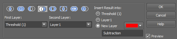
Figure 482.
Choose one type of operation using the icons in the top row:
 AND
AND Intersection of the selected binary layers will be performed.
 OR
OR Union operation will be performed on the selected binary layers.
 Create Subtraction of the Second Layer from the First Layer
 Subtraction of the second layer from the first layer will be performed.
 Create Subtraction of the First Layer from the Second Layer
 Subtraction of the first layer from the second layer will be performed.
 XOR
XOR Non-Equivalence operation will be performed on the selected binary layers.
 EQ
EQ Equivalence operation will be performed on the selected binary layers.
 Copy the first layer
 First layer will be copied to a layer selected in the Insert Result into option.
Select which binary layers will be used in the operation.
Decide in what layer the result of the operation will be stored - either in one of the selected (source) layers or in a New Layer which will be created upon the binary operation start.
Select this option to preview the effect of the operation on the current image.
Procedure
(requires: Automatic Measurement)(requires: Automatic Measurement)
Runs the Binary > Define Threshold command and saves the resulting binary layer as the graticule image.
(requires: Automatic Measurement)(requires: Automatic Measurement)
Opens the binary editor in which it is possible to draw/edit the graticule mask.
See also Drawing tools
(requires: Automatic Measurement)(requires: Automatic Measurement)
Deletes the graticule mask created by either of the commands:
(requires: Automatic Measurement)(requires: Automatic Measurement)
Displays a dialog window which selects a file with the graticule, previously exported via the Binary > Mask > Save Mask command.
(requires: Automatic Measurement)(requires: Automatic Measurement)
Saves the current graticule mask. A Save As Image dialog box is shown.
(requires: Automatic Measurement)(requires: Automatic Measurement)
Sets transparency of the graticule mask. The following options are available:
Only a single pixel contour around the mask is shown.
The mask is shown partially transparent.
The mask is shown in full color without any transparency.
(requires: Automatic Measurement)(requires: Automatic Measurement)
Opens the graticule properties window and selects the Mask type. See Binary > Mask > Mask Properties. Mask will be activated after clicking the button.
(requires: Automatic Measurement)(requires: Automatic Measurement)
Morphological opening performs Erosion followed by Dilation. This has the effect of clearing all objects which are too small with respect to the specified parameters. Larger structures are not significantly affected.
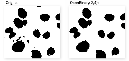
Figure 483. Example
The Open on Binary Image dialog box appears.
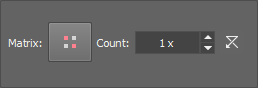
Figure 484.
Click the button to change the structuring element used for this operation. See Structuring Element = Kernel = Matrix.
Number of iterations.
 Reset
Reset Sets the dialog default values.
Select this option to preview the effect of the operation on the current image.
(requires: Automatic Measurement)(requires: Automatic Measurement)
Morphological closing performs Dilation followed by Erosion. It fills all holes in objects which are too small with respect to the specified parameters. Closely neighboring objects get connected.
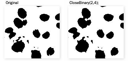
Figure 485. Example
Figure 486.
Click the button to change the structuring element used for this operation. See Structuring Element = Kernel = Matrix.
Number of iterations.
Reset Sets the dialog default values.
(requires: Automatic Measurement)(requires: Automatic Measurement)
Erosion sets each pixel to the value computed as minimum from all pixels in the matrix. Erosion shrinks objects and removes small ones. A non-convex object can split into several parts.
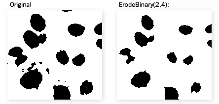
Figure 487. Example
The Erode Binary Image dialog box appears.
Figure 488.
Click the button to change the structuring element used for this operation. See Structuring Element = Kernel = Matrix.
Number of iterations.
Reset Sets the dialog default values.
Select this option to preview the effect of the operation on the current image.
See Also
Binary > Dilate
(requires: Automatic Measurement)(requires: Automatic Measurement)
Dilation sets each pixel to the value computed as maximum from all pixels in the matrix. Dilation expands objects and structures in binary image. Neighboring objects are connected and small holes are filled.
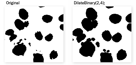
Figure 489. Example
The Dilate Binary Image dialog box appears.
Figure 490.
Click the button to change the structuring element used for this operation. See Structuring Element = Kernel = Matrix.
Number of iterations.
Reset Sets the dialog default values.
Select this option to preview the effect of the operation on the current image.

(requires: Automatic Measurement)(requires: Automatic Measurement)
Removes small objects from binary image. This transformation is also called geodesic opening. First, the image is eroded and small objects disappear. Then the remaining eroded objects are reconstructed to their original size and shape. The advantage of this algorithm is that small objects disappear but the rest of the image is not affected. The function can be performed repeatedly.
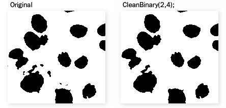
Figure 491. Example
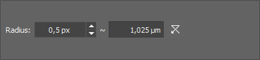
Figure 492.
Click the button to change the structuring element used for this operation. See Structuring Element = Kernel = Matrix.
Number of iterations.
Reset Sets the dialog default values.
(requires: Automatic Measurement)(requires: Automatic Measurement)
Removes small holes from the current binary image.
Fills all holes in the binary image which would be destroyed by Erosion of the specified parameters.
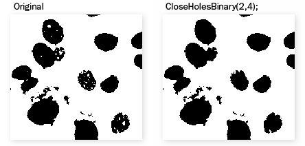
Figure 493. Example
The Close Holes dialog box appears.
Figure 494.
Click the button to change the structuring element used for this operation. See Structuring Element = Kernel = Matrix.
Number of iterations.
Reset Sets the dialog default values.
(requires: Automatic Measurement)(requires: Automatic Measurement)
Smooths binary image contours.
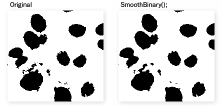
Figure 495. Example
Figure 496.
It is possible to define the strength of the function by specifying the number of iterations.
Reset Sets the dialog default values.
Select this option to preview the effect of the operation on the current image.
(requires: Automatic Measurement)(requires: Automatic Measurement)
Fills holes in a binary layer. Holes which are connected to image borders remain intact.
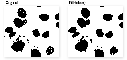
Figure 497. Example
(requires: Automatic Measurement)(requires: Automatic Measurement)
This function expands non-convex binary image objects to their convex boundaries.
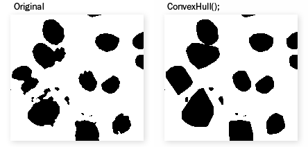
Figure 498. Example
(requires: Automatic Measurement)(requires: Automatic Measurement)
This function transforms the binary layer to its contour.
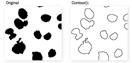
Figure 499. Example

(requires: Automatic Measurement)(requires: Automatic Measurement)
Separates binary objects into multiple smaller objects. The higher the Count, the fewer objects will be separated.
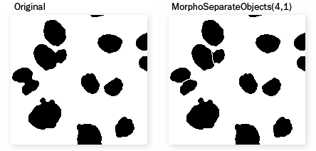
Figure 500. Example
Morpho Separate Objects dialog box appears.
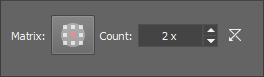
Figure 501.
Click the button to change the structuring element used for this operation. See Structuring Element = Kernel = Matrix.
Number of iterations.
(requires: Automatic Measurement)(requires: Automatic Measurement)
This command deletes every binary object which touches the image border.
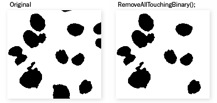
Figure 502. Example
(requires: Automatic Measurement)(requires: Automatic Measurement)
This command can be used for interactive calling of NIS-Elements drawing functions. The Insert dialog box appears.
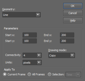
Figure 503.
Select the type of geometry you wish to draw (i.e. one of the following):
Calls the InsertLine function which inserts a line in the image.
Calls the InsertLines function which inserts two parallel lines in the image.
Calls the InsertCircle function which inserts a circle in the image.
Calls the InsertEllipse function which inserts an ellipse in the image.
Calls the InsertRectangle function which inserts a rectangle in the image.
Calls the InsertMarkers function which inserts a grid of markers in the image.
Calls the InsertMarker function which inserts one marker.
Number and type of parameters changes accordingly to the selected geometry.
4 or 8, defines the way a line is drawn. See Connectivity.
The distance between parallel lines. Selected Units are used to specify the coordinates.
You can select a logical operation which will be performed between the existing binary layer and the object(s) being inserted.
Closed shapes can be either filled or hollow. Select TRUE to fill the shape or FALSE to leave it hollow.
Depending on the selected geometry, these parameters define distances significant for each shape. Selected Units are used to specify the distances.
When inserting markers, one of the predefined marker shapes can be selected from a pull-down menu.
These parameters specify orientation of the object in degrees [°].
Depending on the selected geometry, these parameters define coordinates significant for placement of the shape (center for a circle, start/end for a line, etc...). Selected Units are used to specify the coordinates.
Select whether the coordinates/dimensions of the shape will be specified in pixels or in the image calibration units.
Note
This option appears only if the current image is calibrated.
Apply the operation to the current image and close the window.
(requires: Automatic Measurement)(requires: Automatic Measurement)
This function inverts the binary layer. It easies the binary layer definition. You can also invoke this command by pressing Ctrl + G keyboard shortcut.