Adjust Image

Detect
Size
Convert
Rotate
Flip
Clear
None
Low
Medium
High

Increases contrast of the image. It changes intensities of the current image. Hue and saturation are not affected. Intensities are rescaled according to the selected method.
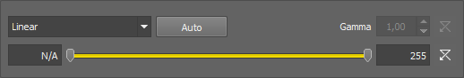
Figure 455.
Options
Sets the Range so that the limits correspond to the minimum and maximum intensities found in the image.
The parameter for the Gamma Correction method. It ranges from 0.05 to 5.00. Set Gamma < 1 to get more information in dark areas or set Gamma > 1 to enhance bright parts of the image.
Set the low/high contrast intensities. Pixels with intensity greater than the high value set will be changed to a pure white, whereas pixels with intensity smaller than the low value set will be changed to pure black (zero). The range itself will be stretched to fit the available intensity range.
Closes the dialog window and applies the contrast settings.
Closes the dialog window without applying the contrast settings.
Opens this help page.
Turns the preview on/off.
See Image processing for description of other settings.
Methods
These transformations stretch the intensity interval defined by the range to the full intensity range using the selected curve. All values outside the range are set to pure black and pure white.
Equalization transformation leads to uniform intensity distribution in the specified interval <Low, High>.
Gamma correction maps the intensity interval <Low, High> according to exponential equation with the gamma parameter.
Balances and adjusts red, green and blue components of the current RGB image. One or two circular probes appear in the image. Move the probes to specify the white point and - optionally - the black point in the image.
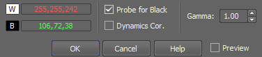
Figure 456.
Shows Red, Green and Blue values for the white probe.
Shows Red, Green and Blue values for the black probe.
Shows the black level probe.
If checked, the values of all color components are recalculated to fit the full intensity range <0,255>.
Coefficient for gamma correction.
Note
Probe assignment is determined dynamically. If you move the red probe (white balance) over an image area which is darker then the area under the green probe (black balance), the probes swap automatically, so the text color in the window swaps as well to indicate the change.
See Image processing for description of other settings.
(requires: Automatic Measurement)
Transforms color image independently for each RGB component.
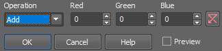
Figure 457.
Type of image transformation.
Adds Red resp. Green resp. Blue value to red resp. green resp. blue component of each pixel.
Subtracts Red resp. Green resp. Blue value from red resp. green resp. blue component of each pixel.
Assigns minimum of red resp. green resp. blue component and Red resp. Green resp. Blue value to relevant component of each pixel.
Assigns maximum of red resp. green resp. blue component and Red resp. Green resp. Blue value to relevant component of each pixel.
Assigns Red resp. Green resp. Blue to red resp. green resp. blue component of each pixel.
Multiplies red resp. green resp. blue component of each pixel by Red resp. Green resp. Blue value.
Divides red resp. green resp. blue component of each pixel by Red resp. Green resp. Blue value.
Value used for red component.
Value used for green component.
Value used for blue component.
Initializes the previous value for selected color.
Apply the operation to the current image and close the window.
See Image processing for description of other settings.
(requires: Automatic Measurement)
Transforms intensities by arithmetic operations.
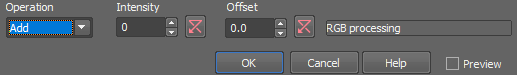
Figure 458.
Type of the image transformation.
Adds Intensity to each pixel.
Subtracts Intensity from each pixel.
Selects minimum between each pixel intensity and Intensity.
Selects maximum between each pixel intensity and Intensity.
Sets the same Intensity to each pixel.
Multiplies each pixel by Intensity.
Divides each pixel by Intensity.
The value used for the arithmetic operation.
Value added to each pixel after the operation. It can be negative.
Displays the preview image.
Apply the operation to the current image and close the window.
See Image processing for description of other settings.

Changes saturation of an RGB image.
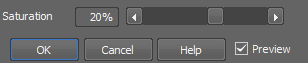
Figure 459.
Expresses the degree of saturation enhancement. Positive values result in lively colors. Negative values de-saturate the image.
See Image processing for description of other settings.
Changes the color tone of an RGB image while maintaining its brightness and saturation.
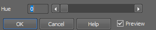
Figure 460.
The hue is measured in degrees on the color wheel <0, 360>.
Apply the operation to the current image and close the window.
Note
This transformation is used for color image enhancement. Note, for instance, that positive hue shift turns blue color towards red.
See Image processing for description of other settings.
Transforms a color image into its complementary color image.
See Image processing for description of other settings.

This command performs smoothing on the color image.
The Smooth Color Image dialog box appears:
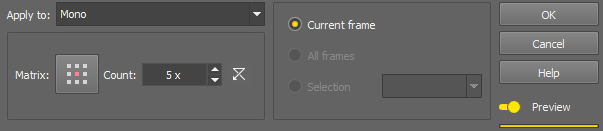
Figure 461.
Click the button to change the structuring element used for this operation. See Matrix.
Number of iterations.
 Reset
Reset Sets the dialog default values.
Process each RGB channel separately or perform the processing on the intensity channel? See Image processing.
Select this option to preview the effect of the operation on the current image.
This function filters small irregularities in images.
See Image processing for description of other settings.

This function sharpens the image.
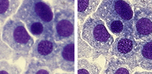
Figure 462. Before - after applying the Sharpen function
See Image processing for description of other settings.
This function slightly sharpens the image.
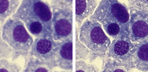
Figure 463. Before - after applying the Sharpen Slightly function
See Image processing for description of other settings.

(requires: Automatic Measurement)
Detects edges by morphological transformations on color images.
The DetectValleys dialog box appears:
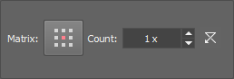
Figure 464.
Click the button to change the structuring element used for this operation. See Matrix.
Number of iterations.
Reset Sets the dialog default values.
Apply the operation to the current image and close the window.
Process each RGB channel separately or perform the processing on the intensity channel? See Image processing.
Note
The Detect Valleys command enhances small dark objects by “Top Hat” morphologic transformation. The size of the selected objects is determined by level of the transformation, which depends on Matrix type and on Number of steps. This command enables the specific segmentation of small objects to the exclusion of larger objects and also can help you in the case of non-homogeneous background.
(requires: Automatic Measurement)
The Detect Valleys (Top Hat) dialog box appears.
Figure 465.
Click the button to change the structuring element used for this operation. See Matrix.
Number of iterations.
Reset Sets the dialog default values.
Apply the operation to the current image and close the window.
Process each RGB channel separately or perform the processing on the intensity channel? See Image processing.
Note
Detect Peaks command enhances small light objects by “Top Hat” morphologic transformation. The size of objects selected is determined by the size of the used structuring element, which depends both on Matrix and Number parameters. This command enables the specific segmentation of small objects to the exclusion of larger objects and also can help you in the case of non-homogeneous background.
(requires: Automatic Measurement)
This command enhances the edges in the image.
See Image processing for description of other settings.
(requires: Automatic Measurement)
Detects edges by morphological transformations of color images.
The Morphologic Gradient dialog box appears:
Figure 466.
Click the button to change the structuring element used for this operation. See Matrix.
Number of iterations.
Reset Sets the dialog default values.
Process each RGB channel separately or perform the processing on the intensity channel? See Image processing.
Note
Morphologic gradient is the difference between dilated and eroded images. It enhances edges.
(requires: Automatic Measurement)
Enhances edges and smooths homogeneous areas in color image. The Delineate dialog box appears:
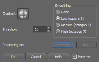
Figure 467.
Size of matrix for gradient detection.
Size of matrix for smoothing.
Threshold value for gradient.
Apply the operation to the current image and close the window.
Process each RGB channel separately or perform the processing on the intensity channel? See Image processing.
Note
In the resulting image, edges are enhanced and smooth areas are more homogeneous.
Creates a pseudo 3-D image. The Relief dialog box appears:
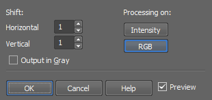
Figure 468.
Sets the shift (in pixels) along X axis.
Sets the shift (in pixels) along Y axis.
If checked, the result of the transformation is a gray image. This option is only applicable to RGB images.
Process each RGB channel separately or perform the processing on the intensity channel? See Image processing.
Note
Superimposition of the original and the shifted image results in a pseudo 3-D image.

Cuts off everything outside the selected area. Selecting this command invokes the crop cursor. Click the primary mouse button and drag to define the cropping area. Adjust the area you want to crop using the red rectangle. Move the white squares on the rectangle edges to adjust its size and move the whole rectangle using the primary mouse button to set its position.
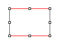
Figure 469. Cropping rectangle
Another way to set the crop is to use the dialog window in which you can specify the Left and Top corners of the rectangle, its Width, Height and the units used (pixels, µm, mm). Once you finish defining the cropping rectangle, confirm it by clicking .
The Draw Rectangle... button hides the dialog window and lets you draw the cropping rectangle manually. Remember Last Settings remembers the crop data which can be reused in future image cropping. If the image being cropped with the remembered data is smaller than the previously cropped one, it may be reduced and moved automatically.
Splits an image into separate tiles. Please see Splitting Large Images for more information.
Using this command it is possible to adjust image dimensions. You can enter the new size as an exact value in pixels or in percents of the current image.
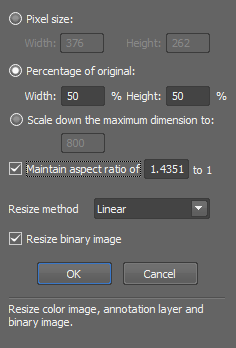
Figure 470.
If this option is chosen, you need to enter new dimensions of the image in pixels.
In case this option is checked, you can enter the size of new image in percents of the current image.
Scales down the image. The longer side of the image is rescaled to the defined number of pixels while the aspect ratio is kept. Shorter side of the image is calculated automatically.
If this option is active, you can enter only one dimension of new image and the other is filled automatically to keep selected aspect ratio. Aspect ratio is computed and prefilled according to your current image dimensions.
You can choose from three different resize algorithms. Try which one works best for your application.
Every NIS-Elements image consist of three (or more) layers (Color, Binary, Annotation...). The Color and annotation layers are linked together, but binary image behaves independently. Checking this option causes simultaneous resizing of both Color and Binary layers.
See Also
Image > Convert > Change Color Depth
This command adds color borders to current image. Selecting this command, the following dialog box appears:
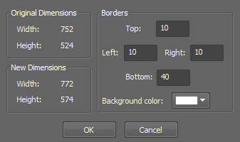
Figure 471.
The left side of window is dedicated to information about image size. The original dimensions are displayed here.
You see the dimensions with borders added.
Four-edit boxes on the right serve for entering the border thickness in pixels. Each edit-box stands for one image side. The color of image frame is possible to define using color picker called Background color.
Opens the Image Binning dialog window enabling to bin the current image based on the binning factor and binning method.
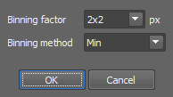
Figure 472.
Binning factor of 3x3 will reduce the area of 9 pixels into a single pixel in the resulting image based on the selected method.
The resulting pixel value will be calculated as maximum, minimum, mean or sum. Sum No Noise - this method brightens the image but does not amplify noise like the Sum method does.
Transforms current color image into gray image.
Note
The resulting intensities are defined for every pixel as an average of red, green and blue component values.
Transforms the current gray image into a color image.
Note
The resulting RGB image consist of three components with identical values. The image looks still grey.
This command changes the color depth of the current image. You can increase or decrease the depth to 8, 10, 12 or 16 bits.
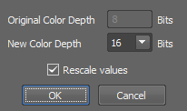
Figure 473.
Displays the color depth of the current image.
Sets a new color depth of your image. You can choose from 8, 10, 12, 16 bit.
If checked the pixel values are mapped to the new range. E.g. when you convert an 8bit image to 16bit and you do not select to rescale values, it results in a completely black image. If the check box was selected, the 8bit 255 value would become 65535 in 16bit etc.
See Also
Image > Size > Resize
Use this command to convert a floating point image to a new standard image. Define which method is used to convert the currently opened floating point image to integer values. Select the bit depth of the new image. Recommended bit depth is displayed below the pull down menu.
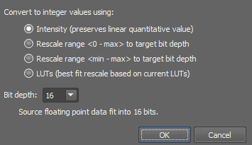
Figure 474.
Converts the image to integer values with minimum loss of quantitative information.
Stretches the interval “0 to image maximimum” to fit the target bit depth.
Stretches the interval “image minimum to image maximimum” to fit the target bit depth.
Stretches the interval “LUTs black slider to LUTs white slider” to fit the target bit depth. See LUTs - Non-destructive Image Enhancement.
Select target bit depth of the resulting image.
Transforms an RGB image to one of its RGB or HSI components. On multichannel images, the HSI color space is not available.
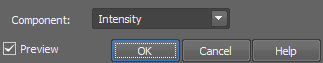
Figure 475.
Select the type of component to be extracted from the pull down menu.
A channel from the RGB color representation.
A component from the HSI color representation. Not available
Note
In the resulting gray image all RGB components are identical and the image is stored in the same way as a “usual” color image.
Adds a new channel to the current image. The following dialog appears:
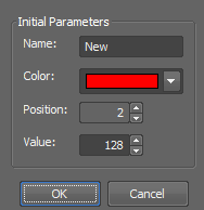
Figure 476.
Enter a name of the new channel.
Select its color from the color palette.
Set its position within the existing channel.
Set the intensity of all pixels of the new channel.
Performs free image rotation. The Rotation dialog box appears:
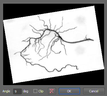
Figure 477.
Defines the angle of the rotation. The rotated image is previewed in the dialog box. The angle is oriented with value ranges from 360 to -360 degree.
Crops the rotated image
Reset Sets the rotation angle back to 0 degree.

This function clears the color layer of a image. All pixel intensities are set to zero.
(requires: Automatic Measurement)
Clears current binary image and sets all pixels to zero.
Note
Performing this command, the ClearBinary function is called and appended to the list of executed functions.