
This procedure is very similar to Automatic Capture with the exception that the user is prompt to capture a new field after the previous field is measured.
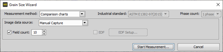
Figure 1372.
If you set the Field Count option, the following window appears when the number of fields is reached.
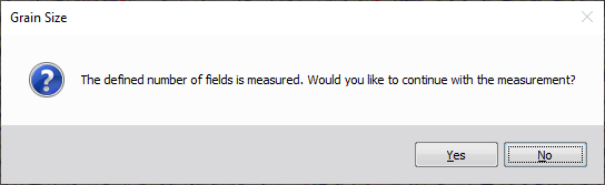
Figure 1373.
Yes
The measurement will go on until the operator terminates it.
No
The measurement will be terminated.
Please see Automatic Capture.