
 Input & Output

Composition of all channels named “All”.
Composition of all fluorescence channels named “Fluo”.
Individual channels.
Matching by channel name - searching the name in a given list of comma separated names.
Matching by channel type - if channel type is Mono/Fluo, matching continues by comparing excitation wavelengths, and if still no match, by emission wavelengths.
{fn}: The complete filename (e.g. 02AU.nd2).
{fnb}: The base part of the filename (e.g. 02AU-enhance.ai.nd2 becomes 02AU-enhance.ai).
{n:xx}: Sequential number with xx indicating the number of digits.
{l:xx} or {li:xx}: Loop counter where l is the loop type and xx is the number of digits.
{ln}: Loop name where l is the loop type (only available for p, w, m, and s).
{lb}: Loop barcode where l is the loop type (only available for p and s).
“xmin” - left edge
“xmax” - right edge
“ymin” - top edge
“ymax” - bottom edge
The “label” column is also mandatory and stands for binary layers name. The “prob” column filled with objects probabilities is optional.
Source table example:
Table 33.
tindex xmin ymin xmax ymax label prob 0 1025 360 1033 373 sperm 0.9998 0 366 478 372 491 sperm 0.9998 1 1186 351 1198 358 sperm 0.9997 1 250 9 263 18 sperm 0.9997 2 66 265 77 272 sperm 0.9995 FilenameSource table location.
LoopThe table dimension representation.
LabelThe desired label searched in source table data.
Minimum probabilityFilter for “prob” column (when present).
Rectangle, CenterSelects one of the binary layer types being loaded (bounding rectangles or centers of original binary objects).
Import and use a GA3 recipe file created before NIS-Elements version 6.10.00.
In NIS-Elements version 6.20.00 and later, it is possible to define the filename using a relative path from the input image file. For example: .\rel\path\example.csv or .\example.csv. You can also use the variables {fn} and {fnb} which can be replaced based on the input image filename or filename. E.g.: for input.nd2 and {fnb}-example.csv -> input-example.nd2.
an ordinary 2D dataset (row x columns) containing atomic datatypes or variable length strings,
a table previously exported using “Table to HDF5” (group of column datasets).
Import and use a GA3 recipe file created before NIS-Elements version 6.10.00.
In NIS-Elements version 6.20.00 and later, it is possible to define the filename using a relative path from the input image file. For example: .\rel\path\example.csv or .\example.csv. You can also use the variables {fn} and {fnb} which can be replaced based on the input image filename or filename. E.g.: for input.nd2 and {fnb}-example.csv -> input-example.nd2.
Inserts a single node with an overlay of all channels present in the current image.
Produces picture outputs representing channels of the source document:
Matching rules can be edited by the user for the correct mapping of channels from a different document. Matching of channels is done in following order:
Unmatched channels are assigned to the rest of the channels with the same channel type (no checking of wavelengths in this step). If there are no such channels available, missing channel is added.
It is possible to assign a custom description to each channel (e.g. nuclei, cell, spots).
Produces picture outputs representing both, the “All” channel composition and the individual channels.
Inserts a parental node with one channel selectable from the list of available channels (Selected) and the second channel with all the remaining channels together (Other).
Creates a new color image (channel) using the specified dimensions (Width, Height) and bit depth and fills it with the specified value.
Inserts all binary layers found in the source image and selected in the drop-down menu.
Inserts a parental node with one output containing the binary layer selectable from the list of available binary layers (Selected) and a second output with all the remaining binaries together (Other).
Inserts a binary node using a segmentation selected in the drop-down menu.
Inserts a table node showing the selected Result from the chosen Analysis and Module.
Loads the result table specified by the Result name from database and appends the content of the connected table to it. When the result table does not exist, the connected table is set as the result. It is useful when some analysis (statistics, classification) has to be calculated over all runs, not just the current one. In such a case use the result R to perform the analysis on.
Loads the result table from a HDF5 file given by the Filename parameter and appends records from node's input table. Table location inside the HDF5 file is defined by the current analysis name and node's output name.
Defines the folder used as an input. Click and select the folder.
Import and Export nodes share some folder path handling and naming conventions.
When exporting files, the path specified in the Folder (or Filename in the case of CSV) dictates where the files will be saved. The path can be either absolute or relative:
If the path starts with a drive letter (C:\ ...), the file will be exported to that absolute path.
If the path is relative (., folder\, or .\folder), the file will be exported relative to the destination file (dst). Typically, dst is the same as src, except in the case of the GA Executor where it might differ.
When using the name field as a format template, placeholders can be included in the name string to customize the output filenames. These placeholders will be replaced as follows:
Note
This does not apply to CSV files, as they produce a single file by concatenating rows.
Additional placeholders are also available:
Example:
{fnb}_M{m:2}_T{t:2} will generate “02AU_M01_T01”, “02AU_M01_T02”, ... and append the appropriate filename extension.
Different loop types and their corresponding identifiers are used in placeholders:
Plate
Well
XY Multi-Point
Time-lapse
Z-Stack
Count
Slide
Region
Temporary
Channel
List separator
Microsoft Excel should use the same List separator value when opening a CSV file so that the CSV file is correctly opened.
In Microsoft Windows 11, the list separator is set in Time & Language > Language & region > Administrative language settings > Formats > Additional settings > Numbers > List separator.
Loads a binary layer consisting of rectangular objects representing bounding rectangles or centers of original binary objects. The main purpose of this node is the visualization of objects predicted by AI nodes. Optionally the objects' probability can be taken into account and objects can be filtered according to it.
The source table is assumed to be accumulated for the whole dimension and the first column represents the dimension index. The following columns are mandatory and represent the bounding rectangles' positions in pixels:
Imports a table from a comma separated values file (.csv). A data type (number or text) is determined for every column. The header (if present) can force the column type and a specific column meaning. Following header syntax is recognized:
Name or Keyword [Unit] : Type
Any name except colon.
For special columns like _Entity, _ObjId or _ObjId3d.
Any unit. This is an optional item.
Is int for integer; number, real, double for real numbers and string, text for strings. This is an optional item.
Source table location.
If left empty, the system locale is used. Otherwise the entered two-letter set 1 locale is utilized.
If the CSV is saved in Czech or French, where the decimal separator is a comma, and by default, the locale in Windows is set to US, where the decimal separator is a dot, the numbers will not be recognized and will be read as text. This can be resolved by specifying "cs" or "fr" in the Locale, and the import will use this information to correctly recognize the numbers.
Is used to delimit columns (comma “,” (default), tabulator “TAB” or semicolon “;”).
Check this item when the first row is a header (not actual data).
Note
Since NIS-Elements version V6.10.01 and onwards the Filename and Location parameter has been removed from the list of available dynamic parameters. If you want to use these dynamic parameters as in the previous versions, please use the following workaround:
Loads a table from HDF5 file.
Table can be:
When the format is not recognized table is not loaded.
Path to the file containing the table.
Group or dataset in the file e.g. /Ga3Tables/Records.
Note
Since NIS-Elements version V6.10.01 and onwards the Filename and Location parameter has been removed from the list of available dynamic parameters. If you want to use these dynamic parameters as in the previous versions, please use the following workaround:
Exports TIFF images to the specified folder with the given name. This action can be used for having a reference when GA3 is used more than once JOBS.
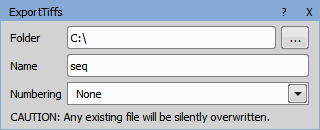
Figure 949.
Path where the TIFF images will be saved.
Name of the TIFF files.
Exports objects from the connected binary layer into .svg images.
Destination folder for saving the created file.
Created file name.
If numbering is set to None, a single file is created. This file is overwritten with every frame of the new data. The two other options create one .svg file per frame:
Sets fill opacity of the exported object.
Sets stroke opacity of the exported object.
Creates new nd2 file from cropped regions of the original one represented as a multipoint loop. Frames are ordered according to the selected column from the input table. Other loops (Timelapse, ZStack) are preserved.
Destination folder for saving the created file.
Created file name.
Suffix of the created files in case of saving to separate files (other loops than Timelapse and ZStack exist).
Column from the input table determining the cropped regions order in the resulting multipoint loop.
Column from the input table determining the center X of the cropped region in pixels.
Column from the input table determining the center Y of the cropped region in pixels.
Width of the cropped region.
Height of the cropped region.
Note
Preview creates a filename with a “Preview” prefix.
Exports the table into a .csv (Comma Separated Values) file.
Name of the file and the path where it will be saved.
Deletes the file content with each GA3 run.
Deletes the file content.
Choose a field separator of the .csv file.
Stores a table into a HDF5 file.
Path to the file containing the table.
Group or dataset in the file e.g. /Ga3Tables/Records.
Sets whether the table is cleared before it is written to or appended.
Note
Preview creates a filename with “Preview” prefix.
Exports the table into a .png image.
Path where the images will be saved.
Name for the image files.
Loads data previously saved with the Input & Output > Temporary > Save Last Color node. The data is shared in the specified loop and kept private in other loops.
Saves the data to temporary storage. The data is shared in the specified loop and kept private in other loops.
Note
The B input must be connected to the Input & Output > Temporary > Load Last Color node to ensure that it is executed before the Save.
Name of the storage used to distinguish the temporary stores.
Loop where the data is shared (<none> to share in all loops).
Loads data previously saved with the Input & Output > Temporary > Save Last Binary node. The data is shared in the specified loop and kept private in other loops.
Saves the data to temporary storage. The data is shared in the specified loop and kept private in other loops.
Note
The B input must be connected to the Input & Output > Temporary > Load Last Binary node to ensure that it is executed before the Save.
Loads data previously saved with Input & Output > Temporary > Save Last Table node. The data is shared in the specified loop and kept private in other loops.
Saves the data to temporary storage. The data is shared in the specified loop and kept private in other loops.
Note
The B input must be connected to the Input & Output > Temporary > Load Last Table to ensure that it is executed before the Save.
Defines which channels (the connected ones) are shown in the wizard, whether autoscale LUTs is turned on and whether a pseudocolor is used for their visualization.
Defines which binary layers (the connected ones) are shown in the wizard, whether the object IDs are shown and how the binary layer transparency is set.
Defines which tables (the connected ones) are shown in the wizard.
Saves all connected channels into the result document. Connected inputs are synchronized by the “ToBeStored” property of the channel outputs present in the analysis.
Saves all connected binaries into the result document. Connected inputs are synchronized by the “ToBeStored” property of the binary outputs present in the analysis.
Saves all connected tables into the result document. Connected inputs are synchronized by the “ToBeStored” property of the table outputs present in the analysis.
Sources have to be added explicitly and the source node needs a GUI for channel mapping or binary selection.