
Run the  Applications > Ratio, Ca2+, FRET > Capture FRET Image command to display the main FRET control panel. Select the appropriate settings and capture the FRET image by the Capture FRET button.
The FRET control panel consists of several sections. In this section, optical configurations which will be used during the acquisition should be assigned to FRET channels.
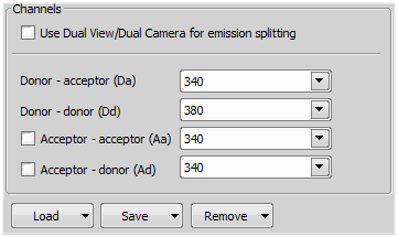
Figure 621.
In this pull-down menu, select an optical configuration that contains Camera settings which shall be used during the FRET image acquisition. If None is selected, the current camera settings will be used.
The FRET image can contain 2-4 channels. Here you can assign an optical configuration to each of them. It is recommended that the optical configuration contains only the filter changer settings.
Note
If the Dual View device is available, it can be used for channel splitting. Then, only one optical configuration for each excitation wavelength will be used. The Dual View device splits the emitted light to two beams filtering different wavelengths, and each of them is captured by only a half of the camera chip.
Dual camera setup is also possible, splitting the different wavelengths between two cameras.
Separate images of the D-labeled and the A-labeled samples must be acquired in order to calibrate the FRET method correctly.
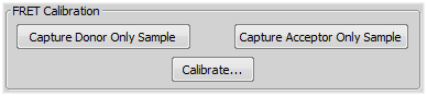
Figure 622.
Insert the D-labeled sample. Press the Capture Donor Only Sample button.
A new image will be captured and named “Donor”.
Insert the A-labeled sample. Press the Capture Acceptor Only Sample button.
A new image will be captured and named “Acceptor”.
Press the Calibrate button to display the calibration dialog.
Select the “Donor” image and the “Acceptor” image in the appropriate pull-down menus.
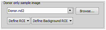
Figure 623.
The Define ROI and the Define Background ROI buttons distinguish the foreground/background parts of the images.
Draw the background/foreground ROIs.
Confirm the calibration by .
Note
Any image file can be used for the calibration. The pull down menu displays the currently opened images. Other images can be reached via the Browse button. If a non-FRET image is used, a window appears where you should map the image channels to FRET channels and select the FRET method.
In this section, select one of the two available FRET methods, Sensitized Emission or Specified bleed through.
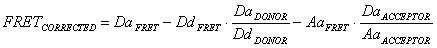
Figure 624. Sentisized Emission
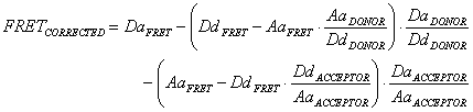
Figure 625. Specified bleed through
Average intensities of assigned FRET image components.
Average intensities of the donor/acceptor-only images.
FRET coefficients
There can be 2 or 4 coefficients used according to the method. Their values are results of the calibration. If the calibration was not performed, you can type the coefficient values manually. The coefficients settings can be saved/loaded.
DaACCEPTOR / AaACCEPTOR
DaDONOR / DdDONOR
DdACCEPTOR / AaACCEPTOR
AaDONOR / DdDONOR