
This panel is used for the preparation of measurement sequences. A set of measurement tools is arranged in five groups which enables anyone to easily define complex measurement sequences which can then be performed repeatedly by an operator. Run the  View > Analysis Controls > Measurement Sequencer - Definition
  to display it.
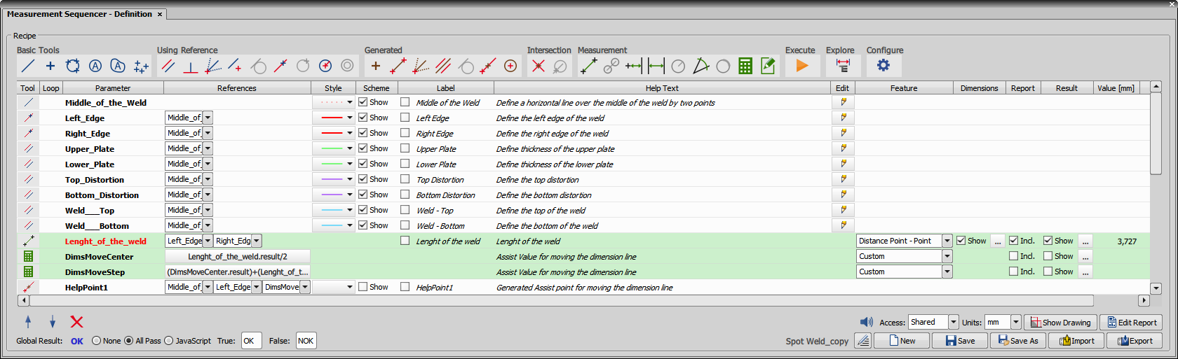
Figure 417. Measurement Sequencer - Definition
Properties of a single step/row
Measurement tool icon.
The name of the measured feature (e.g. Line_length_A).
Some features can be based on other - e.g. line parallel to an existing line. Select the related feature names from the pull-down menu(s).
Color and thickness of the feature line in the image. A transparent color can be selected so that the drawn measurement object is invisible in the image.
Show the feature in the drawing?
Display a label containing the measured value in the image?
Click this  button to draw the object to the image.
Some tools can measure more than one feature (e.g.: distance to a circle can be measured to the center or to the edge). Specify the right option in the Feature column.
Select the box if you want to show dimension lines of the measured value in the image. Click to select color and thickness.
Select Incl. to include the feature in the report (Report Editing).
Check Show to view the measured value and the validation result directly in the result table. Click to set the measurement Limits, JavaScript Condition, what happens to the validation when a measurement is skipped (Skip Measurement Behavior - see below), validation texts (Passed/Failed), Visual Warning (yellow-orange Validation field indicating the exceeded min/max limits), Conditional Action with a JavaScript Condition, message (Show Message) or a selected action (Perform Action).
Skip Measurement Behavior automatically fills in the measurement value based on the settings made here when the user skips the measurement. If Pass, Fail or N/A is selected, this value is automatically assigned to the skipped measurement. The User Defined option enables the user to assign the Passed, Failed or N/A value to the measurement right in the moment of skipping the measurement or section simply by clicking on one of the three buttons.
Displays values measured during the test run.
Displays the measured units.
Basic Tools
 Line
Line Draws a simple line.
 Point
Point Draws a simple point.
 3 Points Arc
 Draws an arc by clicking 3 points on it.
 3 Points Circle
 Draws a circle by clicking 3 points on it.
 Circle
 Draws a circle by clicking and dragging.
 Autodetect Circle
 Automatically detects a circle with its center in the center of gravity of the clicked object (confirm its detection by the secondary mouse click). The circle has the same area as the detected object.
 Autodetect Contour
 Automatically detects the contour of the clicked object. The contour can be adjusted using the mouse wheel and has to be confirmed by the secondary mouse click. Parameters of the contour can be later used in the  Custom Expression.
 Set of Points
 Draws multiple points.
Using Reference
Reference object can be drawn to any existing line, point or circle.
 Parallel Line
 Perpendicular Line
 Draws a line perpendicular to an existing line. Specify the line in the References column.
 Line with Reference Point
 Draws a line starting in an existing point or center of a circle. Specify the point or the circle in the References column.
 Free Normal Line
 Draws a line perpendicular to an existing point or center of a circle. Specify the point or the circle in the References column.
 Tangential Line
 Point on Line
 Point on Circle
 Circle from Point
 Concentric Circle
Generated
Generated object is drawn automatically based on the selected existing objects.
 Point in XY
 Generates a point from the XY coordinates. Specify the point position in the References column.
 Line Between Points
 Generates a line between two selected points or circle centers. Specify the points or the circles in the References column.
 Line From Point Under Angle
 Generates a line from an existing point/circle center under a specified angle. Specify the point and angle in the References column.
 Line Between Parallel Lines
 Generates a line between two existing parallel lines in the specified distance from the first line to towards the second one. Specify the lines and distance in the References column.
 Tangential Line
 Generates a tangent to an existing circle using a point or circle center specifying the direction of the intersection. Specify the point or the circle center in the References column.
 Point on Line in a Distance from Point
 Circle Based on Center Point and Radius
Intersection
Draws an intersection of the selected existing objects.
 Point by Lines Intersection
 Point by Line and Circle or Contour Intersection
Measurement
Performs a measurement between the selected objects.
 Point to Point Distance
 Measures the distance between two points or circle centers. Specify the points or the circles in the References column.
 Distance of Centers or Contours
 Measures the distance between the centers of two circles. Specify the circles in the References column and their center/edge relation in the Feature column.
 Point to Line Distance
 Measures the perpendicular distance between the line and a point/circle center. Specify the line and point/circle center in the References column.
 Parallel Lines Distance
 Measures the distance between two parallel lines. Specify the lines in the References column.
 Circle Radius
 Measures the circle radius or diameter. Specify the circle in the References column and the measured feature in the Feature column.
 Angle
Angle Measures the angle between the two lines. Specify the lines in the References column and specify the angle range in the Feature column.
 Arc
Arc Measures the circle arc. Specify the circle and two points/circle centers which define the arc in the References column. Also specify the angle range in the Feature column.
Custom Click to set any custom calculation combining features of previously defined objects, measurement results, global variables or cells from Excel. Predefined Functions and a custom JavaScript can be used as well.
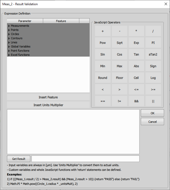
Figure 419. Custom Expression
Insert Feature inserts the selected feature into the expression below. Insert Units Multiplier inserts a “_unitsMult” multiplier which is used to convert your expression to units selected in the Measurement Sequencer - Definition Units drop-down menu. By default, micrometer unit is selected (“_unitsMult” =1).
 User Input
  Execute
 Reset
Reset  Explore
Opens the Measurement Explorer (Measurement Explorer) organizing the previously defined measurement sequences (see Measurement Sequencer - Definition).
 Configure
Opens the Configuration dialog window with the following options:
Variable Parallel Lines Length dynamically changes the line length when defining lines dependent on different lines.
Arrow Dimensions shows arrows for all finished Measurements.
Sync Colors displays the text label in the color set in the Dimension Properties on a black background. The selected color Style affects the parameter name, color of the object in the original image, in the Measurement Sequencer - Definition and Measurement Sequencer - Run and in the report.
Black/White displays black label text on a white background.
Draw red border if result failed in validation displays a red border around each result which is found invalid.
After the definition is made, labels can be moved around to a different position so that they do not overlap. This label shift can be remembered if Remember last position if moved manually is checked.
Draw/Measure new definition objects immediately after insertion replaces clicking the button for each defined feature. If it is turned on, the user draws objects immediately after defining the feature. Force set dimension line endpoints to pixel center places the dimension lines right in the middle of the image pixels thus not resulting in sub-pixel measurements below the camera resolution.
Note
Properties settings are saved together with the definition.
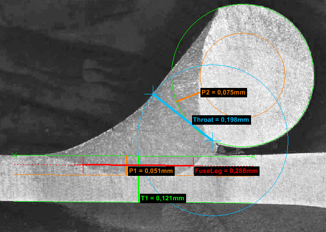
Figure 420. Measurement sequence executed on a weld sample.


These buttons move the current row up/down in the sequence definition table.
 Remove
 Deletes the selected record(s).
Global Result
Global result is turned off.
If each measurement result passes its defined limits, the global result becomes valid.
Use the button to add a JavaScript condition to the global result validation. It can include any combination of the defined object features and measurement results.
Defines the text shown for the measurements which pass.
Defines the text shown for the measurements which do not pass.
Name of the measurement definition.
More Options
 Sound
Sound Turns the object definition sound on/off.
By default, all definitions created by a user are Shared and any other user can access them. If this option is switched to Private, only the user who created the definition can see it. The access state is saved together with the definition.
If the Modify shared Sequencer definitions option is unchecked (Edit > Options > User rights > Privileges > Modify shared Sequencer definitions) shared sequences can be used by any user but cannot be edited.
If the Remove shared Sequencer results option is unchecked (Edit > Options > User rights > Privileges > Remove shared Sequencer results) any results acquired on a shared definition cannot be deleted by other users but the definition creator.
Sets the measurement units.
Sets the measurement precision.
 Show Drawing
 Displays a diagram showing the defined measurement. loads the diagram using the current image.
 Edit Report
 Reveals the report panel enabling to define a custom report (Report Editing).
 Edit Name/Description
 Enables the user to edit the name and description of the current measurement definition.
 New
New Creates a new blank definition.
 Save
Save Overwrites the current definition in the database.
 Save As
 Saves the current definition into the database with a defined name and description notes.
 Import
 Opens the saved definition from a .msd or .bin file.
 Export
 Saves the current definition into a .msd (Measurement Sequencer Definition) file.
 Preview Report
Context Menu over Step(s)
Moves the selected step(s) one row up.
Moves the selected step(s) one row down.
Creates a section from the selected steps. Once a measurement hits a section, the section can be skipped as a whole, i.e. all steps inside the section are skipped at once. Use  Skip Section in the View > Analysis Controls > Measurement Sequencer - Run
  panel.
Removes the selected section.
Creates a loop from the selected steps. Once a measurement hits the loop, it repeats and generates new results for the looped measurement again and again until the user exits the loop (by a secondary-mouse click). This is useful e.g. when the user measures an unspecified number of objects not known in advance.
Removes the selected loop.
Duplicates the selected step(s).
Removes the selected step(s).