


Turn the Background ROI ON, or set any existing ROI as background (right-click a ROI and select Use as Background ROI).
Place the ROI so that it would define the background you would like to subtract.
Invoke the Subtract Background command. The average value of background is subtracted from each channel.
Select the shifting units - voxels (in 3D), pixels (in 2D) or micrometers.
Define XY(Z) step size for the arrow and spin buttons.
Select a check box next to one channel to set it as reference. This channel will be always visible.
Click a table row to give focus to the channel you want to shift (the row gets highlighted). Use the arrow buttons to shift the channel as necessary.
It is a good idea to open the ND image in another view (such as volume view) to check whether the shift between channels has been corrected.
Click to apply the shifts on all frames.
 Image > Contrast
Increases contrast of the image. It changes intensities of the current image. Hue and saturation are not affected. Intensities are rescaled according to the selected method.
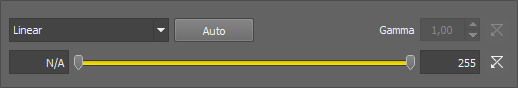
Figure 608.
Options
Sets the Range so that the limits correspond to the minimum and maximum intensities found in the image.
The parameter for the Gamma Correction method. It ranges from 0.05 to 5.00. Set Gamma < 1 to get more information in dark areas or set Gamma > 1 to enhance bright parts of the image.
Set the low/high contrast intensities. Pixels with intensity greater than the high value set will be changed to a pure white, whereas pixels with intensity smaller than the low value set will be changed to pure black (zero). The range itself will be stretched to fit the available intensity range.
Type
Image > Adjust Image > White Balance Balances and adjusts red, green and blue components of the current RGB image. One or two circular probes appear in the image. Move the probes to specify the white point and - optionally - the black point in the image.
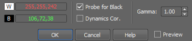
Figure 609.
Note
Probe assignment is determined dynamically. If you move the red probe (white balance) over an image area which is darker then the area under the green probe (black balance), the probes swap automatically, so the text color in the window swaps as well to indicate the change.
See Image processing for description of other settings.
Image > Adjust Image > RGB Transformation Transforms color image independently for each RGB component.
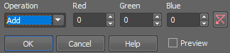
Figure 610.
Type of image transformation.
Adds Red resp. Green resp. Blue value to red resp. green resp. blue component of each pixel.
Subtracts Red resp. Green resp. Blue value from red resp. green resp. blue component of each pixel.
Assigns minimum of red resp. green resp. blue component and Red resp. Green resp. Blue value to relevant component of each pixel.
Assigns maximum of red resp. green resp. blue component and Red resp. Green resp. Blue value to relevant component of each pixel.
Assigns Red resp. Green resp. Blue to red resp. green resp. blue component of each pixel.
Multiplies red resp. green resp. blue component of each pixel by Red resp. Green resp. Blue value.
Divides red resp. green resp. blue component of each pixel by Red resp. Green resp. Blue value.
See Image processing for description of other settings.
Image > Adjust Image > Intensity Transformation Transforms intensities by arithmetic operations.
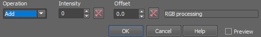
Figure 611.
See Image processing for description of other settings.
Image > Adjust Image > Change Saturation 
Changes saturation of an RGB image.
Figure 612.
See Image processing for description of other settings.
Image > Adjust Image > Change Hue Changes the color tone of an RGB image while maintaining its brightness and saturation.
Figure 613.
Note
This transformation is used for color image enhancement. Note, for instance, that positive hue shift turns blue color towards red.
See Image processing for description of other settings.
Image > Adjust Image > Complement Colors 
Transforms a color image into its complementary color image.
See Image processing for description of other settings.
Image > Background > Subtract Background Using Background ROI This command subtracts background defined by the background probe from the whole image.
Subtracting background
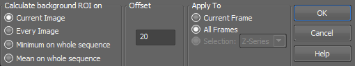
Figure 614.
See Image processing for description of other settings.
Image > Background > Subtract Background Using Reference This command subtracts pixel values of the reference image from the current image. The reference image is created by the Reference > Current Image -> Reference menu command.
Figure 615.
Image > Background > Subtract Background Using Constant Subtracts a value from each channel separately.
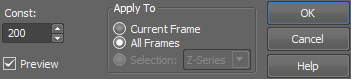
Figure 616.
See Image processing for description of other settings.
Subtracts a value from the selected channel.
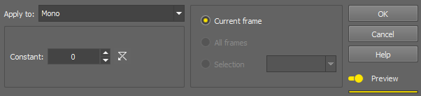
Figure 617.
See Image processing for description of other settings.
Image > Smooth 
This command performs smoothing on the color image.
The following dialog box appears:
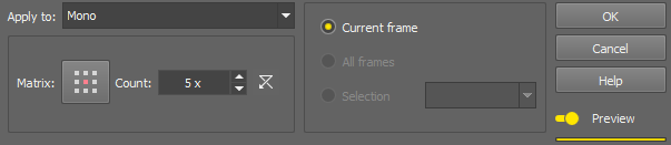
Figure 618.
Click the button to change the structuring element used for this operation. See Matrix.
Process each RGB channel separately or perform the processing on the intensity channel? See Image processing.
Image > Sharpen 
This function sharpens the image.

Figure 619. Before - after applying the Sharpen function
Image > Sharpen Slightly This function slightly sharpens the image.
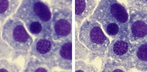
Figure 620. Before - after applying the Sharpen Slightly function
Image > Detect > Detect Valleys 
Detects edges by morphological transformations on color images.
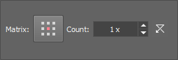
Figure 621. Dialog options
Click the button to change the structuring element used for this operation. See Matrix.
Process each RGB channel separately or perform the processing on the intensity channel? See Image processing.
Note
The Detect Valleys command enhances small dark objects by “Top Hat” morphologic transformation. The size of the selected objects is determined by level of the transformation, which depends on Matrix type and on Number of steps. This command enables the specific segmentation of small objects to the exclusion of larger objects and also can help you in the case of non-homogeneous background.
Image > Detect > Detect Peaks The Detect Valleys (Top Hat) dialog box appears.
Figure 622.
Click the button to change the structuring element used for this operation. See Matrix.
Process each RGB channel separately or perform the processing on the intensity channel? See Image processing.
Note
Detect Peaks command enhances small light objects by “Top Hat” morphologic transformation. The size of objects selected is determined by the size of the used structuring element, which depends both on Matrix and Number parameters. This command enables the specific segmentation of small objects to the exclusion of larger objects and also can help you in the case of non-homogeneous background.
Image > Detect > Gradient Morpho Detects edges by morphological transformations of color images.
The following dialog appears:
Figure 623.
Click the button to change the structuring element used for this operation. See Matrix.
Process each RGB channel separately or perform the processing on the intensity channel? See Image processing.
Note
Morphologic gradient is the difference between dilated and eroded images. It enhances edges.
Image > Morphology > Open Performs morphological opening on current color image. Morphological opening is erosion followed by the same number of dilations. The transformation removes small light objects. If the structuring element dimension has an odd value, there are two enhanced pixels in structuring element depicting centers: one for erosion and the other for dilation.
The following dialog appears.
Figure 624.
Click the button to change the structuring element used for this operation. See Matrix.
Image > Morphology > Close Performs morphological closing on the current color image.
The following dialog appears.
Figure 625.
Click the button to change the structuring element used for this operation. See Matrix.
Morphological closing is a dilation followed by the same number of erosions. Small dark areas are removed by this transformation. If the structuring element dimension has an odd value, there are two enhanced pixels in structuring element depicting centers: one for erosion and the other for dilation.
Image > Delineate Enhances edges and smooths homogeneous areas in color image. The Delineate dialog box appears:
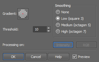
Figure 626.
Process each RGB channel separately or perform the processing on the intensity channel? See Image processing.
Note
In the resulting image, edges are enhanced and smooth areas are more homogeneous.
Image > Relief Creates a pseudo 3-D image. The Relief dialog box appears:
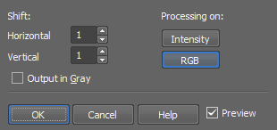
Figure 627.
If checked, the result of the transformation is a gray image. This option is only applicable to RGB images.
Process each RGB channel separately or perform the processing on the intensity channel? See Image processing.
Note
Superimposition of the original and the shifted image results in a pseudo 3-D image.
Image > Crop 
Cuts off everything outside the selected area. Selecting this command invokes the crop cursor. Click the primary mouse button and drag to define the cropping area. Adjust the area you want to crop using the red rectangle. Move the white squares on the rectangle edges to adjust its size and move the whole rectangle using the primary mouse button to set its position.
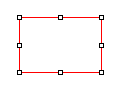
Figure 628. Cropping rectangle
Another way to set the crop is to use the dialog window in which you can specify the Left and Top corners of the rectangle, its Width, Height and the units used (pixels, µm, mm). Once you finish defining the cropping rectangle, confirm it by clicking .
The  Draw Rectangle... button hides the dialog window and lets you draw the cropping rectangle manually. Remember Last Settings remembers the crop data which can be reused in future image cropping. If the image being cropped with the remembered data is smaller than the previously cropped one, it may be reduced and moved automatically.
Image > Split Image Splits an image into separate tiles. Please see Splitting Large Images for more information.
Image > Size > Resize Using this command it is possible to adjust image dimensions. You can enter the new size as an exact value in pixels or in percents of the current image.
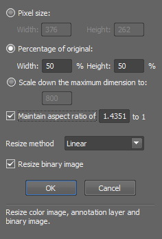
Figure 629.
In case this option is checked, you can enter the size of new image in percents of the current image.
Scales down the image. The longer side of the image is rescaled to the defined number of pixels while the aspect ratio is kept. Shorter side of the image is calculated automatically.
If this option is active, you can enter only one dimension of new image and the other is filled automatically to keep selected aspect ratio. Aspect ratio is computed and pre-filled according to your current image dimensions.
See Also
Image > Convert > Change Color Depth
Image > Size > Canvas Size This command sets the dimensions of current image. Selecting this command displays the following window:
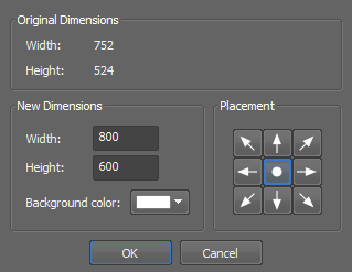
Figure 630.
The upper part of window is informational and shows current image dimensions. You can set new dimensions using the Width and Height edit-boxes. The image will not be resized, but cropped (in case of new dimensions are smaller than the old ones) or placed in the image, surrounded by borders in background color (in the case of new dimensions are grater than original image). You can define the placement of an old image in the new image using the arrow button tool.
Image > Size > Add Borders This command adds color borders to current image. Selecting this command, the following dialog box appears:
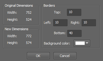
Figure 631.
Image > Size > Binning Opens the Image Binning dialog window enabling to bin the current image based on the binning factor and binning method.
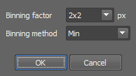
Figure 632.
Image > Convert > Convert to Gray Transforms current color image into gray image.
Note
The resulting intensities are defined for every pixel as an average of red, green and blue component values.
Image > Convert > Convert to RGB Transforms the current gray image into a color image.
Note
The resulting RGB image consist of three components with identical values. The image looks still grey.
Image > Convert > Convert to Multichannel This command changes the image (image) type of the current RGB image to Multichannel. The Custom channel is appended.
Image > Convert > Change Color Depth This command changes the color depth of the current image. You can increase or decrease the depth to 8, 10, 12 or 16 bits.
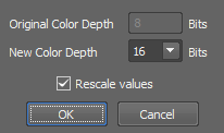
Figure 633.
See Also
Image > Size > Resize
Image > Convert > Convert Floating Point Image to Use this command to convert a floating point image to a new standard image. Define which method is used to convert the currently opened floating point image to integer values. Select the bit depth of the new image. Recommended bit depth is displayed below the pull down menu.
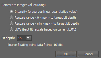
Figure 634.
Stretches the interval “0 to image maximimum” to fit the target bit depth.
Stretches the interval “image minimum to image maximum” to fit the target bit depth.
Stretches the interval “LUTs black slider to LUTs white slider” to fit the target bit depth. See LUTs - Non-destructive Image Enhancement.
Image > Convert > Extract Component Transforms an RGB image to one of its RGB or HSI components. On multichannel images, the HSI color space is not available.
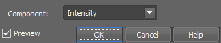
Figure 635.
Note
In the resulting gray image all RGB components are identical and the image is stored in the same way as a “usual” color image.
Image > Convert > Add New Component Adds a new channel to the current image. The following dialog appears:
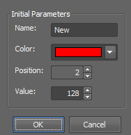
Figure 636.
Image > Rotate > Rotate By Degree Performs free image rotation. The Rotation dialog box appears:
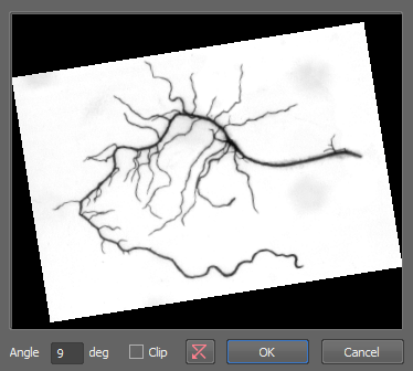
Figure 637.
Image > Rotate > Rotate in Center Performs a rotation via line. Drawing the line you specify only the angle of rotation. The center of the rotation will be in the center of the image. Defined line in the image is rotated to become horizontal using the sharp angle. Rotated image is computed from the source using 4-neighbourhood.
Image > Rotate > Rotate Level Horizontal Performs rotation via line. Line in the image is rotated to become horizontal. Drawing the line you specify the center and the angle of rotation. Defined line in the image is rotated to become horizontal using the sharp angle. Rotated image is computed from the source using 4-neighbourhood.
Image > Rotate > Rotate Level Vertical Performs rotation via line. Line in the image is rotated to become vertical. Drawing the line you specify the center and the angle of rotation. Defined line in the image is rotated to become vertical using the sharp angle. Rotated image is computed from the source using 4-neighbourhood.
Image > Rotate > Rotate Rectangle Enables you to select a rectangular shaped part of an image and adjust its final orientation. The rest of the image will be cut off.
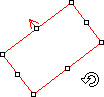
Figure 638.
Place, resize and rotate the red rectangle. When you confirm the action by right click, the command will crop the image and rotate the selected area, so that the red arrow will point upwards.
Image > Shift > Right This command moves the current image or a selected component by one pixel in the defined direction. The pixels that overflow the image borders appear on its opposite side.
When using this command via the key shortcut (Ctrl+Shift+Arrow) on a single component, all components are displayed together until the Ctrl+Shift keys are released.
Image > Shift > Left This command moves the current image or a selected component by one pixel in the defined direction. The pixels that overflow the image borders appear on its opposite side.
When using this command via the key shortcut (Ctrl+Shift+Arrow) on a single component, all components are displayed together until the Ctrl+Shift keys are released.
Image > Shift > Up This command moves the current image or a selected component by one pixel in the defined direction. The pixels that overflow the image borders appear on its opposite side.
When using this command via the key shortcut (Ctrl+Shift+Arrow) on a single component, all components are displayed together until the Ctrl+Shift keys are released.
Image > Shift > Down This command moves the current image or a selected component by one pixel in the defined direction. The pixels that overflow the image borders appear on its opposite side.
When using this command via the key shortcut (Ctrl+Shift+Arrow) on a single component, all components are displayed together until the Ctrl+Shift keys are released.
Image > Clear > Clear Color 
This function clears the color layer of a image. All pixel intensities are set to zero.
Image > Clear > Clear Annotations Clears current annotation layer and sets color of all pixels to transparent.
Image > Align Channels Opens the Align Channels dialog window enabling to manually shift each channel in the X, Y or Z direction.
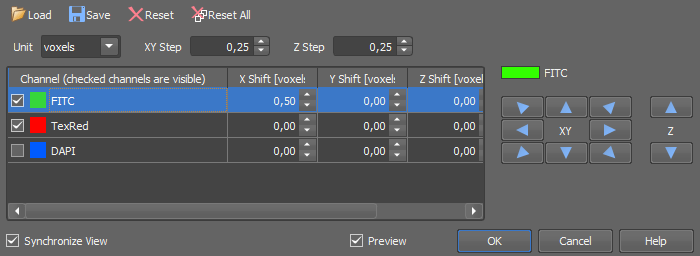
Figure 639.
Example procedure
Align Channels
 Load
Load Save
Save Reset
Reset Reset All