
Open image, prepare for measurement
Open your image containing layers to be measured.
Calibrate your image (if not already calibrated) using
 Calibration > Recalibrate Document.
Run the
Applications > Layer Thickness Measurement > Measure Layers command.Select the proper layer mode using the tabs (Linear, Circular, General, CaloTest). The measuring procedure is specific to each layer mode.
Define baseline for the measurement
Define Layers to be measured
For each layer:
Define a layer using one of the following detection methods:
 Autodetect
 Automatically detects a layer. After clicking into a homogeneous area, the system detects a region of similar pixels. Fine-tune the selection using the mouse wheel and confirm it by the secondary mouse click.
 Draw
Draw Runs the binary editor which can be used to define your layer with various drawing tools. Once you are finished with the layer drawing, click
 Exit Editor or press Esc.
See Binary Editor.
 Threshold
 Opens the Define Threshold dialog window used for thresholding your layer (see
Binary > Define Threshold ).In the Gaps drop-down menu choose the behavior which will be use if your image contains gaps and holes (click on
 to see the explanation).
Check whether this layer will be measured (Measure checkbox).
Set optional limits of the measurement (check Limits and fill in the Min and Max value).
Resolve overlapping layers
Select the layers which are visible in the image by clicking left from the layer name in the Layers Definition table. Selected layers are highlighted blue with a green point in the Sel. column. Hold down Ctrl to select multiple layers. Change order of the selected layer(s) in the list using
 Move Up,
  Move Down.
Define the Keep Edge feature for each layer. If the binary layers of your sample overlap, it is necessary to define which portions of the overlap are used for the measurement of each layer. This depends on the order in the Layers Definition table and on the Keep Edge setting:
NoneThe currently defined layer is cropped by both neighbouring layers defined in the definition table if their binary image is overlapping.
TopThe currently defined layer is cropped by the layer below and not cropped by the layer above in the definition table.
BottomThe currently defined layer is cropped by the layer above and not cropped by the layer below in the definition table.
BothThe currently defined layer will not be cropped by any other layer.
Click
 Adjust Edges if your layers overlap and you want to apply the order set in the Keep Edge definition to solve the overlapping areas.
Adjust measurement settings
If you want to limit the measurement on sides of the image, use
 Apply Limits and drag the red vertical lines by the white square to limit the measurement only to the inside. For circular measurement click two points to define the circular sector. To turn the limits off, click Apply Limits again. To change the limits, use
  Redefine limits.
Optionally define vertical intersections over which the measurement is made. The number of vertical lines (green color in the image) can be specified in the Number of Intersections or their spacing can be set in the Intersection Every option.
Handle the results
At any time you can delete the defined binary layers together with the measured results after clicking
 Clear Data.
Results of the measurement are displayed in the results table on the right. You can export the results to a report (
 Export to Report), to MS Excel (
  Export to Excel), to a .csv file (
  Export to File), to windows clipboard (
  Export to Clipboard), you can also export raw data to MS Excel ( Raw data to Excel), to a .csv file ( Raw Data to File), or to windows clipboard ( Raw Data to Clipboard). Clicking on Edit Report... reveals the report panel enabling to define a custom report (see Report Editing).
To save the current results into the database, use
 Save to History. These results can then be found in the Measurement Explorer panel (see Measurement Explorer).
Save Measurement Settings (optional)
To save the Layer Thickness Measurement settings, use
 Save Definition, name the .bin file and specify its location. To load a previously saved definition, click
  Load Definition.
  Reset Definition clears the dialog window settings.
 Define Baseline
 Define Radius
 Define Polyline
 New Layer
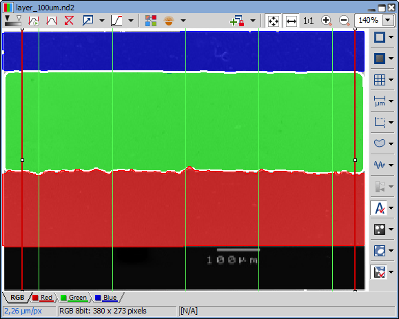
Figure 1334. Image window showing that the linear layer measurement will be performed over the intersection lines (green) inside the limited area (red lines).
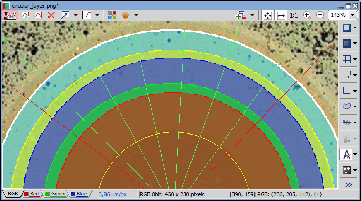
Figure 1335. Image window showing the circular layer measurement on five layers
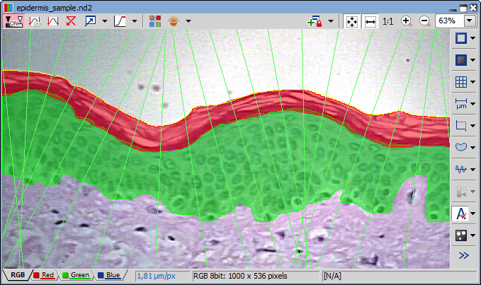
Figure 1336. Image window showing the general layer measurement on two layers with 20 intersections