
If devices different than Illumination and Piezo Z are dragged&dropped into the sequence table a dialog window pops-up. The device behavior has to be selected. Two options are offered:
This type of element determines at which point in time a voltage change is made. E.g. all values for the TTL Output are low (by default) until a frame containing this type of element is executed and changes the value from low to high to all frames hereafter. Double click the element and edit its behavior.
For Focus Offset a dialog window is opened automatically. Enter the Focus Offset value and click .
For (Calibrated) Analog Output set a Value [V] or choose a Function. For the functions Sinus, Cosinus, Saw and Rectangle, set the Polarity of the function, set the Synchronization (Experiment Begin = beginning phase of the signal is at the beginning of the experiment). Then set the Amplitude, Period and Offset (from 0 V). General function is non-periodical and enables the user to enter the switching points manually. Use the edit box to write down each Time [ms] and Value [V] change point in the following notation: time1,voltage1 time2,voltage2 time3,voltage3 etc. To load a predefined set from a *.txt file use . Points in the *.txt file can be separated either by a space or enter character.
Note
Before the beginning of each exposure phase, there is a period of about 20 µs (depending on the camera accuracy) during which it is not possible to change the voltage. This stretch of time is highlighted by a red line showing the user the real progression of the function being set.
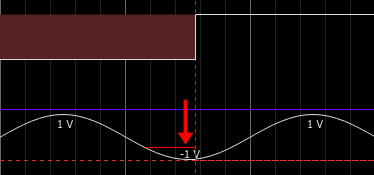
Figure 1040.
For TTL Output define its State (Low/High) or Assign the Current Value and select when will the Change be made (Exposure Start, Exposure End or Dead Time Start).
Shutter, Switcher and Filter wheel use this type of logic by default.
This type of element changes the value only over frames where it is present. Fields without this element use the default value taken from the Optical Configuration. Double click the element and edit its behavior.
For Focus Offset a dialog window is opened automatically. Enter the Focus Offset value and click .
For (Calibrated) Analog Output set the Power or Assign the Current Value, choose over how many frames it will be Repeated, select when will the change Start At and Stop At (Exposure Start/End or Dead Time Start/End or Next Exposure Start) and define the Offset if necessary. Pulsed illumination can also be set (see: Creating illumination patterns).
Settings for TTL Output is the same as for (Calibrated) Analog Output (see above) except choosing the State (Low/High) in the first combo box.
Note
Default state of each device is determined by its Optical Configuration ( Calibration > Optical Configurations
  ).
).
Live view does not follow the IS setup, so previewing should be done via /.
Even after pressing you can change the power of any laser line by clicking on the corresponding cell and changing its power. The new value will propagate to the NI card waveform and will be applied.
For IS examples, please see Usage Examples.