
Figure 1031.
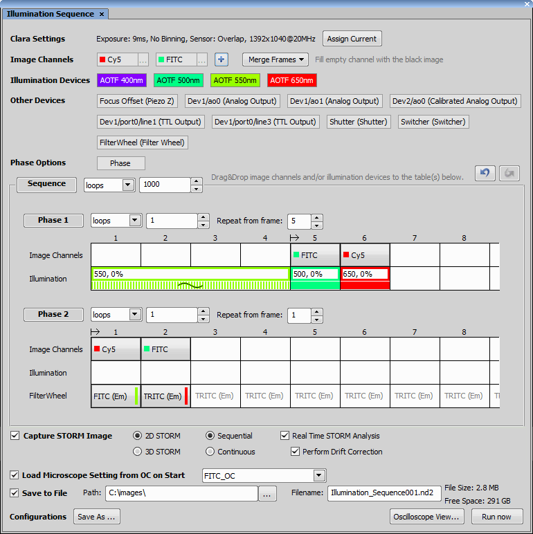
This row shows parameters influencing the timing of the camera which is used for capturing. Use the button to assign current camera settings to be used for capturing. In case of multi-camera mode, one camera will be used for IS, defined in a combo box, where the user selects the active camera. The camera I/O signal is the source for the IS timing. In case of dual camera drivers (dual Andor, dual Flash 4.0, dual Neo/Zyla) the timing of the master is shown.
Note
List of supported cameras can be found here: Supported cameras.
This area aggregates all channels necessary for your experiment. All defined channels will be contained in the resulting ND2 file. Start by clicking on the  button, enter the Name of your channel, enter its wavelength (EM) and choose its Color from the combo box. The real color of the wavelength is offered first, followed by pseudo colors. Click and add more channels if necessary or edit the current ones by clicking next to their name. EM value defined in IS channel is written in the metadata of the resulting ND2 file inside the Acquisition details pane (see:
  File > Image Properties). Channel color defined in the IS will be used as a pseudo color for a given channel in the ND2 document.
This option is available only if more than one channel is defined. A number of channels in the target ND2 document will correspond to the number of channels defined in the Image Channels section.
If group frames to channel is not selected, for each index of the camera frame with an imaging channel, a document index will be created with the number of planes corresponding to the number of channels.
Overall, three options for merging frames are available. Fill empty channel with black image option captures an image only over frames where each channel is placed. Frames where the particular channel is missing are filled with black. Fill empty channel with the last image option uses the last frame of the particular channel and copies it to frames where the channel is missing till a new frame of the channel is updated. Group frames to channel option waits until one frame of each channel is acquired. Then a merged image containing all defined channels is created.
Only NIDAQ based devices which enable TTL Triggering can be used. Each laser line of the used illumination device is represented by a draggable color rectangle. The last “Dummy” device is not a real illumination device but can be used to create a delay after a phase.
Note
List of supported illumination devices can be found here: Supported illumination devices.
To use DMD with IS, you have to configure its logical devices inside the device manager ( Devices > Device Manager  ) using . Switch the HW Interface to USB/PCIe + Ext Trig in the DMD Configuration dialog.
If Keep Level stimulation type is used with DMD, Stimulation patterns (Calibration Grid, Full On, Full Off, Custom) can be selected from the Pattern combo box available after double-clicking on the element. uses the currently selected ROI as the stimulation pattern.
If Use Pattern stimulation type is used, Stimulation patterns can be selected from the Pattern combo box at the top of the dialog window displayed after double-clicking on the element. Single Pulsed illumination (Follow Exposure illumination mode) and time and cycle duration (Continuous illumination mode) are supported. Offset, pulsed illumination using a time period or computed period filling selected time cannot be used together with DMD (Custom illumination mode).
Check Advanced in the Pattern Properties and click to set an advanced pattern.
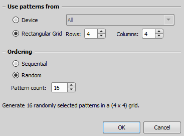
Figure 1032. Advanced Pattern Settings dialog window
Use patterns from
Generates a grid on the live image based on the specified rows/columns.
Ordering
Stimulates through the pattern/grid in a sequential order.
Stimulates through the pattern/grid in a random order.
Number of patterns/grid areas which will be illuminated.
Illumination sequence supports only the 1-bit level grayscaling mode (mirror grayscaling button on the DMD Pad needs to be unselected).
Other NIDAQ devices supporting IS include: Analog Output, Calibrated Analog Output, Filter Changer, Piezo Z, Shutter, Switcher and TTL Output.
Note
Only NIDAQ cards which support TTL Output triggering can be used. Analog Outputs of internal cards are always triggerable.

 Undo/Redo
 These buttons implement a standard undo/redo functionality.
A phase of any sequence consists of rectangular cells. Each cell has a length of the camera exposure. To create a sequence, fill the cells with particular elements (Channels, Illumination devices, Other Devices) by dragging&dropping their element (rectangular) into the corresponding row of the Phase table.
Each row of the Phase table belongs to the corresponding device displayed on the left. By default, two rows are available (Image Channels and Illumination), however more rows are created if Other Devices are dragged&dropped into the table area.
Next to the Phase caption name you can define the number of loops which will be performed or a time duration. If Repeat from frame is used, the loop is run from the defined frame on every phase repeat (excluding the first one which starts always from the beginning). Phase length is determined by its first and last element.
Phases can be organized inside the sequence by dragging&dropping their caption vertically. Phases can be deleted by dragging&dropping their caption outside the dialog window. They can also be cleared, duplicated and deleted on the context menu. To change the position and order of any Phase, simply drag-drop the elements in its table, use Shift for multi selection and Ctrl for copying the selection into different cells.
Contains all dragged&dropped Image Channels. On a double-click, or context menu over a channel placed inside the table, there is an option to enter the amount of frames over which the channel will be captured. In case of dual view or dual camera setup, two rows of image channels named Camera #1 and Camera #2 are available.
The illumination row contains all dragged&dropped illumination devices. The top of each cell shows the illumination wavelength and its power. The bottom half of the element shows the illumination pattern. To edit the illumination pattern, double click the element in the phase table or right-click on it and choose Edit (see: Creating illumination patterns).
Note
Illumination power can also be changed during runtime by clicking on the illumination element.
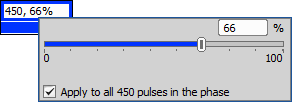
Figure 1033.
If a device other than Illumination or Channel is dragged&dropped inside the Phase table, a new row aggregating this type of device is created. To edit this item, simply double-click on it or right-click and choose Edit.
If the N-STORM device is connected, use this option to capture a STORM image. If you are using a device with a cylindrical lens and want to detect the Z dimension of the molecules, switch to 3D STORM. In other cases use 2D STORM. After defining your illumination sequence, evaluate whether it is Sequential (excitation, then acquisition) or Continuous (excitation and acquisition at the same time). Real Time STORM Analysis determines whether the molecules are detected during the acquisition. If so, the result contains image data and molecules. Perform Drift Correction detects any sample drift made during the image acquisition. If the system finds a drift, turn on the  Drift Correction inside the Molecules Options (Molecule Options) dialog window to compensate for the drift.
This combo box loads the microscope settings of Other Devices from your Optical Configuration. The setting will then be used as a starting state before executing the experiment.
Specifies the folder where your new ND2 file will be saved.
Enter a name of the ND2 file which will be created.
Click to save the current IS settings. Enter a name and click . A new button is created. If multiple settings are created, you can easily switch between them by clicking their buttons. To delete a setting, simply drag-drop its button outside the IS dialog window or use the context menu over the button to delete or overwrite its configuration.
Shows a diagram view of the current IS which will be created. buttons jump to the beginning of the chosen phase. button updates the oscilloscope view if any changes were made to the sequence.
Starts the currently defined experiment.